Urban road and construction method thereof

A technology for roads and cities, applied in the field of urban roads and their construction, can solve the problems of reduced road driving safety, affecting the protective effect of guardrails, and difficult disassembly, etc., so as to avoid adverse effects, simple and orderly construction steps, and high construction efficiency high effect

Pending Publication Date: 2022-07-08
龙德建设有限公司
0 Cites 0 Cited by

AI-Extracted Technical Summary

Problems solved by technology

[0004] And because the vehicle will contact and rub against the guardrail at the same time when it collides with the guardrail, in order to avoid scratching the vehicle, the existing roads also use rotating barrel guardrails, which can greatly absorb the energy by converting the impact force into rotational kinetic energy. The impact force is strong and the impact is reduced, and when friction occurs with the vehicle, it can also rotate to relieve force and reduce s...

Method used

Because road body 1 comprises cushion layer 25, base layer 26 and asphalt layer 27 laid successively from bottom to top, reasonable arrangement between layer and layer ensures the structural strength of road body 1, improves the use of road body 1 life.
Owing to being provided with caulking groove 22 at the top of nesting 10, and elastic washer 23 is provided with at the bottom of caulking groove 22, and elastic washer 23 adopts rubber material to make, and elastic deformation ability is better, then can be screwed compression member 9 Make its bottom embedded in the slot 22, then the elastic washer 23 will be elastically deformed when it is squeezed by the pressing part 9, so that it will reversely apply an upward thrust to the pressing part 9, so that the pressing part can 9 is pressed more tightly, which effectively improves the locking effect on the threaded rod 8, and since the holding runner 24 is arranged on the top of...

Abstract

The invention discloses an urban road and a construction method thereof, and relates to the technical field of road engineering.The urban road comprises a road body, reinforcing guardrails are arranged on the two sides of the road body, each reinforcing guardrail comprises a plurality of stand columns, upper handrails and lower handrails are arranged on the stand columns, and a plurality of anti-collision assemblies are arranged between the upper handrails and the lower handrails; the anti-collision assembly comprises a fixing base arranged on the lower handrail, a supporting rod is hinged to the fixing base, an anti-collision rotating cylinder is detachably connected to the supporting rod, a threaded rod is connected to the end, away from the fixing base, of the supporting rod, a pressing piece is in threaded connection with the threaded rod, and an embedding sleeve used for embedding the threaded rod is arranged on the upper handrail. And a cover shell is detachably mounted at the opening of the nest. The anti-collision rotary drum has the beneficial effects that the anti-collision rotary drum of the urban road is extremely convenient and easy to disassemble and assemble, the protection effect of a reinforced guardrail can be guaranteed all the time, so that the driving safety of the road is guaranteed, and the construction method of the urban road is high in safety and high in construction efficiency.

Application Domain

FencingTraffic signals +2

Technology Topic

Driving safetyHandrail +5

Image

  • Urban road and construction method thereof
  • Urban road and construction method thereof
  • Urban road and construction method thereof

Examples

  • Experimental program(1)

Example Embodiment

[0041] The technical solutions in the embodiments of the present invention will be clearly and completely described below with reference to the accompanying drawings in the embodiments of the present invention. Obviously, the described embodiments are only a part of the embodiments of the present invention, but not all of the embodiments. Based on the embodiments of the present invention, all other embodiments obtained by those of ordinary skill in the art without creative efforts shall fall within the protection scope of the present invention.
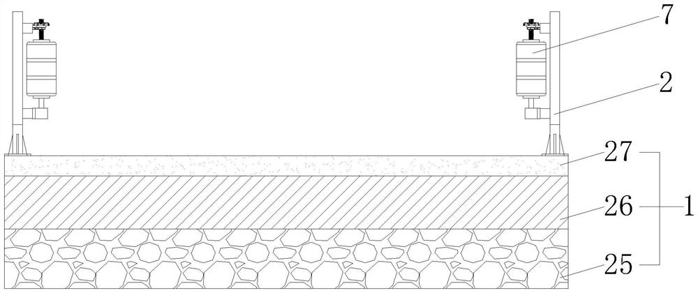
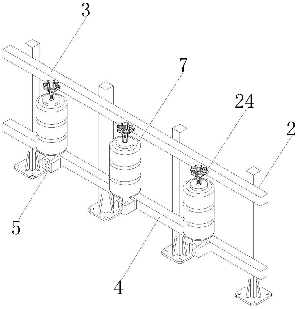
[0042] see Figure 1-8 As shown, an urban highway includes a highway body 1, and the highway body 1 includes a cushion layer 25, a base layer 26 and an asphalt layer 27 laid in sequence from bottom to top, and reinforced guardrails are provided on both sides of the highway body 1, and the reinforced guardrail includes several Upright column 2, an upper railing 3 and a lower railing 4 are arranged on the upright column 2, and a number of anti-collision components are arranged between the upper railing 3 and the lower railing 4, and the anti-collision component includes a fixed seat 5 arranged on the lower railing 4. A support rod 6 is hinged on the fixed seat 5, and an anti-collision drum 7 is detachably connected to the support rod 6, and a threaded rod 8 is connected to the end of the support rod 6 away from the fixed seat 5, and the threaded rod 8 is threaded. A pressing piece 9 is connected, a nest 10 for the threaded rod 8 to be embedded is provided on the upper rail 3, and a cover shell 11 is detachably installed at the opening of the nest 10, on the nest 10 and the cover shell 11 Both are provided with semicircular grooves matching with the threaded rod 8 , wherein a lower support piece 20 is fixedly connected to the support rod 6 , and an upper support piece 21 is threadedly connected to the threaded rod 8 .
[0043] see Image 6 , Figure 7 As shown, two connecting rods 12 parallel to each other are arranged on the cover shell 11, and a clamping block 13 is provided at the end of the connecting rod 12 away from the cover shell 11, and a connecting rod 12 is provided on the nest 10 for the insertion of the connecting rod 12. The slot 14 is provided, and the two sides of the nest 10 are provided with a card slot 15 for the card block 13 to be inserted into, and the card slot 15 and the slot 14 communicate with each other.
[0044] see Image 6 , Figure 8 As shown, a movable groove 16 for the support rod 6 to be inserted into is opened on the fixed seat 5, and a support rod 17 is arranged inside the movable groove 16, and a rotating ball 18 is connected to one end of the support rod 6 inside the movable groove 16, The rotating ball 18 is rotatably connected to the support rod 17 , a groove 19 for restricting the rotation of the support rod 6 is opened on the outer wall of the fixed seat 5 , and the groove 19 and the movable groove 16 communicate with each other.
[0045] see image 3 , Figure 4 , Image 6 , Figure 7 As shown, the top of the nest 10 is provided with an embedded groove 22 for the bottom of the pressing member 9 to be embedded, and an elastic washer 23 is provided at the bottom of the embedded groove 22. The elastic washer 23 is made of rubber material and is provided on the top of the pressing member 9. There is a holding wheel 24 .
[0046] Since there are reinforced guardrails on both sides of the highway body 1, the reinforced guardrails include an upper railing 3 and a lower railing 4, and several anti-collision components are arranged between the upper railing 3 and the lower railing 4, and the anti-collision components include an anti-collision drum 7. When installing the anti-collision drum 7 on the reinforced guardrail, you can first put the anti-collision drum 7 into the support rod 6, then hold the threaded rod 8 and push it upward until the threaded rod 8 is embedded in the nest 10, and then Install the cover shell 11 to the opening of the nest 10 to realize the positioning of the threaded rod 8, and finally screw the pressing member 9 downward to make it interfere with the nest 10 to realize the locking of the threaded rod 8, so as to complete the prevention The installation of the collision drum 7, then when the vehicle collides with the reinforcement guardrail, it will come into contact with the anti-collision drum 7, then the anti-collision drum 7 will rotate relative to the support rod 6, thereby converting the impact force into rotational kinetic energy, which can Greatly absorbs the impact force and reduces the impact, and when the anti-collision drum 7 is deformed and damaged, it is only necessary to screw up the pressing member 9 to release the locking of the threaded rod 8, and then remove the cover shell 11 from the opening of the nest 10. By removing it, the limit on the threaded rod 8 can be released, so that the threaded rod 8 can be moved downward to drive the support rod 6 to swing, so that the anti-collision drum 7 can be directly removed from the support rod 6, then through this The first arrangement makes the disassembly and assembly of the anti-collision drum 7 extremely convenient and simple, so that the anti-collision drum 7 can be disassembled and replaced at any time, and the protective effect of the guardrail can be always strengthened, thereby ensuring the driving safety of the highway.
[0047] Since the cover shell 11 is detachably installed at the opening of the nest 10 , when the cover shell 11 is removed from the nest 10 , the blocking block 13 can be pressed, so that the blocking block 13 is retracted inward and removed from the card slot 15 so that the connecting rod 12 can be pulled out from the slot 14, and then the cover shell 11 can be removed, and when the cover shell 11 is installed on the nest 10, the connecting rod 12 only needs to be inserted into the slot 14. , the connecting rod 12 will drive the card block 13 to be inserted into the slot 14, and the card block 13 will be squeezed inward by the inner wall of the slot 14, and will expand until it moves to the position of the card slot 15. 13 is limited and locked, so that the installation of the cover shell 11 can be realized, then through this setting, the disassembly and assembly of the cover shell 11 on the nest 10 becomes more convenient and simple, so that the disassembly and assembly of the anti-collision drum 7 is made. become more convenient and simple.
[0048] Since the support rod 6 is hinged on the fixed seat 5, when the support rod 6 is moved downward, the rotating ball 18 is driven to rotate relative to the support rod 17 until the support rod 6 collides with the inner wall of the movable slot 16, and the movable slot 16 The inner wall limits the position of the support rod 6, so that the support rod 6 cannot continue to rotate, so that the support rod 6 is kept vertically arranged, which facilitates the disassembly and assembly of the anti-collision drum 7 sleeved on the support rod 6. 6 is fixedly connected with a lower support piece 20, and is threadedly connected with an upper support piece 21 on the threaded rod 8, then after the anti-collision drum 7 is sleeved into the support rod 6, the anti-collision drum can be removed by the lower support piece 20. 7 Hold the bottom, and then screw the upper support piece 21 downward continuously and approach the top of the anti-collision drum 7, so as to limit the anti-collision drum 7 between the upper support piece 21 and the lower support piece 20 to avoid the anti-collision rotation. The drum 7 slides up and down when being impacted, thereby ensuring the use effect of the anti-collision drum 7 .
[0049] Since the top of the nesting 10 is provided with an embedded groove 22, and the bottom of the embedded groove 22 is provided with an elastic washer 23, the elastic washer 23 is made of rubber material and has good elastic deformation ability, then the pressing member 9 can be screwed to make the bottom If it is embedded in the insert groove 22, the elastic washer 23 will be elastically deformed when it is pressed by the pressing member 9, so that an upward thrust will be applied to the pressing member 9 in the opposite direction, so that the pressing member 9 can be pressed. Tighter, effectively improving the locking effect of the threaded rod 8, and since the holding wheel 24 is provided on the top of the pressing member 9, when the pressing member 9 needs to be screwed, the holding wheel 24 can be held When force is applied, the setting of the holding wheel 24 can provide a force application point for the operation of screwing the pressing member 9 , so that the operation of screwing the pressing member 9 becomes easier and labor-saving.
[0050] Since the highway body 1 includes the cushion layer 25 , the base layer 26 and the asphalt layer 27 laid sequentially from bottom to top, the layers are arranged reasonably, ensuring the structural strength of the highway body 1 and improving the service life of the highway body 1 .
[0051] A construction method for an urban highway, comprising the following steps:
[0052] 1) According to the urban highway design specification, use the theodolite to locate the highway center line in advance, release the stake number, bolt the stakes on both sides, and record the data;
[0053] 2) Before construction, place warning signs at both ends of the road, and semi-enclose the construction site with enclosures;
[0054] 3) During construction, the line is first laid out according to the center line of the road, and then excavated by the excavator to dig out the trench;
[0055] 4) Lay the cushion layer and the base layer in sequence in the trench, compact it with a press after the paving, and cover it with felt in time, and sprinkle water for more than a week;
[0056] 5) First clean the surface of the base layer, then sprinkle a small amount of water, and then spread the emulsified asphalt, and then lay the asphalt layer after the emulsified asphalt is spread;
[0057] 6) Install reinforced guardrails on both sides of the surface of the asphalt layer, first install columns along the edge of the road, then install upper railings and lower railings on the columns, and finally install anti-collision components between the upper railing and the lower railing;
[0058] 7) After the installation of the reinforced guardrail, the strength test shall be carried out, and the acceptance shall be carried out after the test is passed.
[0059] The urban highway construction method of the invention has the advantages of fast construction, high safety, low cost, simple and orderly construction steps, and high construction efficiency. It can ensure construction safety and avoid adverse effects on the surrounding environment of the construction site. The strength test is carried out after the installation of the reinforced guardrail to ensure the installation quality.
[0060] It will be apparent to those skilled in the art that the present invention is not limited to the details of the above-described exemplary embodiments, but that the present invention may be embodied in other specific forms without departing from the spirit or essential characteristics of the invention. Therefore, the embodiments are to be regarded in all respects as illustrative and not restrictive, and the scope of the invention is to be defined by the appended claims rather than the foregoing description, which are therefore intended to fall within the scope of the claims. All changes within the meaning and range of the equivalents of , are included in the present invention. Any reference signs in the claims shall not be construed as limiting the involved claim.
[0061] In addition, it should be understood that although this specification is described in terms of embodiments, not each embodiment only includes an independent technical solution, and this description in the specification is only for the sake of clarity, and those skilled in the art should take the specification as a whole , the technical solutions in each embodiment can also be appropriately combined to form other implementations that can be understood by those skilled in the art.

PUM

no PUM

Description & Claims & Application Information

We can also present the details of the Description, Claims and Application information to help users get a comprehensive understanding of the technical details of the patent, such as background art, summary of invention, brief description of drawings, description of embodiments, and other original content. On the other hand, users can also determine the specific scope of protection of the technology through the list of claims; as well as understand the changes in the life cycle of the technology with the presentation of the patent timeline. Login to view more.

Similar technology patents

Bumper device for data storage apparatus

InactiveUS20050259352A1reduce shock
Owner:SEAGATE TECH LLC

Shifting manipulation apparatus for vehicle

InactiveUS20150167842A1reduce shock
Owner:HYUNDAI MOTOR CO LTD

Roller chain transmission device

InactiveUS20070270261A1reduce shockreduce engagement noise
Owner:TSUBAKIMOTO CHAIN CO

Classification and recommendation of technical efficacy words

  • Quick and easy disassembly
  • reduce shock

Multifunctional tripod with accurate leveling function

PendingCN107966140Aeasy levelingQuick and easy disassembly
Owner:SHANDONG UNIV

Soft tissue debridement self-retaining retractor

InactiveCN103211631AQuick and easy disassemblyeasy to carry
Owner:THE THIRD AFFILIATED HOSPITAL OF THIRD MILITARY MEDICAL UNIV OF PLA

Portable field quick drying box for macro-fungi specimen

InactiveCN111692844AQuick and easy disassemblyeasy to carry
Owner:庆元县食用菌产业中心

Cabinet cold channel elevated base and elevated base system

ActiveCN104619143AQuick and easy disassemblyImprove installation efficiency
Owner:WUXI KANGBEI ELECTRONICS EQUIP

Sealed small low-impact release screw bolt

InactiveCN101875404Areduce shockstrong connection
Owner:BEIJING INSTITUTE OF TECHNOLOGYGY

Electronic product placing frame with damping effect

InactiveCN108458043Aprevent accidental slippingreduce shock
Owner:佘峰

Exoskeleton device suitable for supporting of radiation-proof clothes

ActiveCN106493715AReduce the burden on the human bodyreduce shock
Owner:SOUTHEAST UNIV

Noise reduction device, compressor and air conditioner

Owner:GREE ELECTRIC APPLIANCES INC OF ZHUHAI
Why Eureka
Try Eureka