Refrigeration compressor shell, refrigeration compressor and refrigeration system

A technology for refrigeration compressors and refrigeration systems, applied in refrigerators, compressors, refrigeration components, etc., can solve problems such as complex structures and increased costs, and achieve the effects of reducing volume, avoiding liquid shock, and being simple and complex

Active Publication Date: 2022-07-08
TSINGHUA UNIV
View PDF5 Cites 0 Cited by
  • Summary
  • Abstract
  • Description
  • Claims
  • Application Information

AI Technical Summary

Problems solved by technology

[0004] At present, the regenerator is usually installed separately. On the one hand, the structure of the vapor compression refrigeration system becomes complicated, and additional space is required to arrange the regenerator. On the other hand, the use of the regenerator as a separate component also increases the cost.

Method used


Image

  • Refrigeration compressor shell, refrigeration compressor and refrigeration system
  • Refrigeration compressor shell, refrigeration compressor and refrigeration system
  • Refrigeration compressor shell, refrigeration compressor and refrigeration system

Examples


Embodiment 1

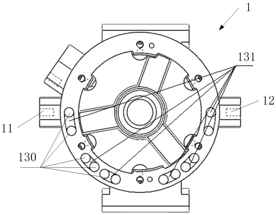
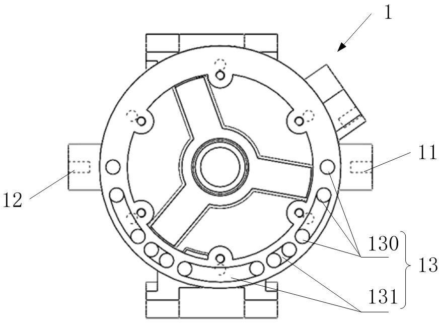
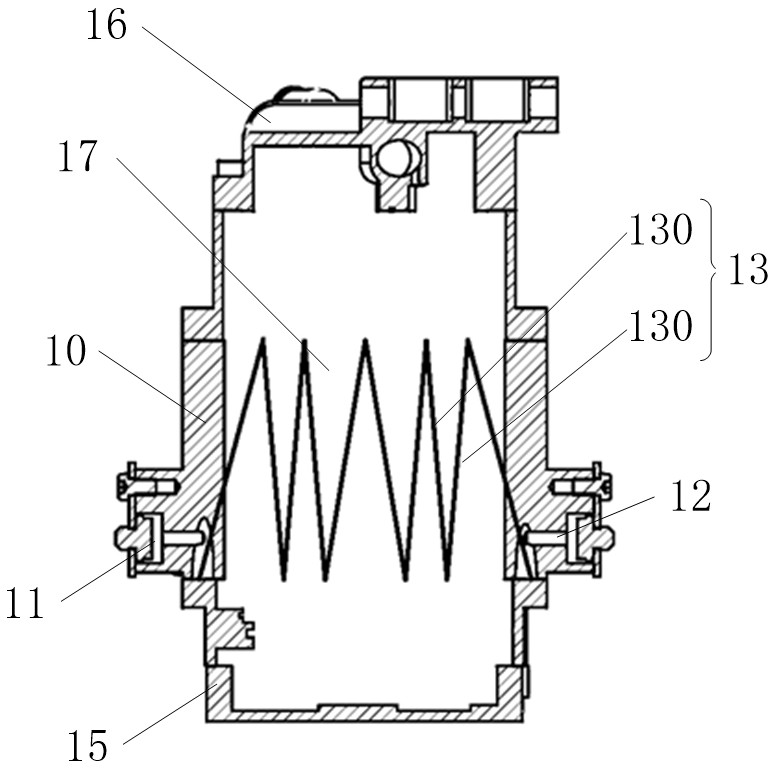
[0066] see Figure 1 to Figure 10 As shown, the first embodiment of the present application provides a refrigeration compressor casing 1, the refrigeration compressor casing 1 includes a casing body 10 surrounding a compression cavity 17 (for example, see image 3 ), the compression cavity 17 is used for the passage of the refrigerant medium, and the refrigerant medium is compressed and pressurized in the compression cavity 17 .

[0067] The casing body 10 has a specified length direction and a circumferential direction. Here, the length direction of the casing body 10 is defined as the direction in which the refrigerant enters and exits with respect to the compression cavity 17 , and the circumferential direction of the casing body 10 is defined as a direction perpendicular to the casing. The section in the longitudinal direction of the body body 10 faces the direction defined by the outer peripheral edge of the cross section obtained by cutting the casing body 10 . For exam...

Embodiment approach

[0147] In the optional solution of this embodiment, the boundary line delimiting all the heat exchange channels 13 is defined as the heat exchange area. Regarding the size of the heat exchange area, the heat exchange area covers part or all of the circumferential direction of the housing body 10, Regarding another embodiment in which the size of the heat exchange area is set, the heat exchange area extends over part or all of the longitudinal direction of the casing body 10 .

[0148] That is, the heat exchange area may extend over the entire circumference of the case body 10 and over the entire length of the case body 10 , or the heat exchange area may cover the entire circumference of the case body 10 and over the case body 10 in the lengthwise direction, or the heat exchange area may extend over a circumferential portion of the casing body 10 and over the entire lengthwise direction of the casing body 10, or the heat exchange area may extend over a circumferential portion of...

Embodiment 2

[0161] Embodiment 2 provides a refrigeration compressor. This embodiment includes the refrigeration compressor casing in Embodiment 1. The technical features of the refrigeration compressor casing disclosed in Embodiment 1 are also applicable to this embodiment. Embodiment 1 The technical features of the disclosed refrigeration compressor housing will not be described repeatedly.

[0162] combine Figure 1 to Figure 9 and see Figure 10 As shown, the refrigeration compressor 2 provided in this embodiment includes a refrigeration compressor casing 1, so that the working parts in the refrigeration compression chamber of the refrigeration compressor 2 are supported and protected by the refrigeration compressor casing 1, and the working parts in the refrigeration compression chamber of the refrigeration compressor 2 are supported and protected by the refrigeration compressor casing 1. The casing 1 provides an access point for the refrigeration compressor 2 to be connected to the ...


PUM


Abstract

The invention relates to the technical field of refrigeration equipment, in particular to a refrigeration compressor shell, a refrigeration compressor and a refrigeration system. The refrigeration compressor shell comprises a shell body, wherein a compression cavity is defined by the shell body; the shell body is provided with a first inlet, a first outlet and a heat exchange runner, and the heat exchange runner and the compression cavity are located on the outer side and the inner side of the inner surface of the shell body correspondingly; the heat exchange runner is provided with a first end and a second end, the first end communicates with the first inlet, and the second end extends to communicate with the first outlet along a preset path relative to the first end. The refrigeration compressor comprises the refrigeration compressor shell. The refrigeration system comprises the refrigeration compressor. According to the refrigeration compressor shell, the refrigeration compressor and the refrigeration system, the heat exchange medium exchanges heat with the shell body and the refrigeration medium, so that the refrigeration medium can be at least subjected to heat regeneration, and the refrigeration compressor shell can also be used for cooling the refrigeration medium and a motor.

Description

technical field [0001] The present application relates to the technical field of refrigeration equipment, and in particular, to a refrigeration compressor housing, a refrigeration compressor and a refrigeration system. Background technique [0002] In the vapor compression refrigeration system, the refrigeration compressor lifts the refrigerant from low pressure to high pressure, and makes the refrigerant circulate continuously, so that the system continuously discharges the internal heat to the environment higher than the system temperature. [0003] In vapor compression refrigeration systems, regenerators are usually used to increase the temperature of the refrigerant, such as figure 1 As shown, the regenerator superheats the refrigerant flowing back to the refrigeration compressor, so as to improve the circulation efficiency and refrigeration capacity of the vapor compression refrigeration system where the refrigeration compressor is located. [0004] At present, the reg...

Claims


Application Information

Patent Timeline
Patent Type & Authority Applications(China)
IPC IPC(8): F04B39/12F04B39/06F25B31/02F25B40/06F25B31/00
CPCF04B39/121F04B39/06F25B31/02F25B40/06F25B31/006
Inventor 史琳
Owner TSINGHUA UNIV
Why Eureka
Try Eureka