Strain value correction method under condition of arrangement deviation of precise diaphragm strain element

A component layout and precision diaphragm technology, applied in the direction of electromagnetic measuring devices, electric/magnetic solid deformation measurement, etc., can solve the problems of small strain measuring point area, strange test orientation, high cost of precision structure, etc., and achieve the effect of improving accuracy

Pending Publication Date: 2022-07-08
INST OF ROCK & SOIL MECHANICS CHINESE ACAD OF SCI
View PDF8 Cites 0 Cited by
  • Summary
  • Abstract
  • Description
  • Claims
  • Application Information

AI Technical Summary

Problems solved by technology

For conventional devices, when the strain gauges are pasted tilted, the original strain gauges can be cleaned and pasted again to the correct position; but for precision structures, cleaning the original strain gauges and pasting them again cannot ensure the integrity of the precision devices, and even affect the integrity of the precision devices. Normal use; at the same time, such precision structures are often expensive and require high integrity
In addition, some special-shaped structures have reasons such as small strain measuring point area and singular test orientation, which makes it difficult or even impossible to accurately arrange strain elements, resulting in inherent test errors in the arranged strain elements

Method used


Image

  • Strain value correction method under condition of arrangement deviation of precise diaphragm strain element
  • Strain value correction method under condition of arrangement deviation of precise diaphragm strain element
  • Strain value correction method under condition of arrangement deviation of precise diaphragm strain element

Examples


Embodiment 1

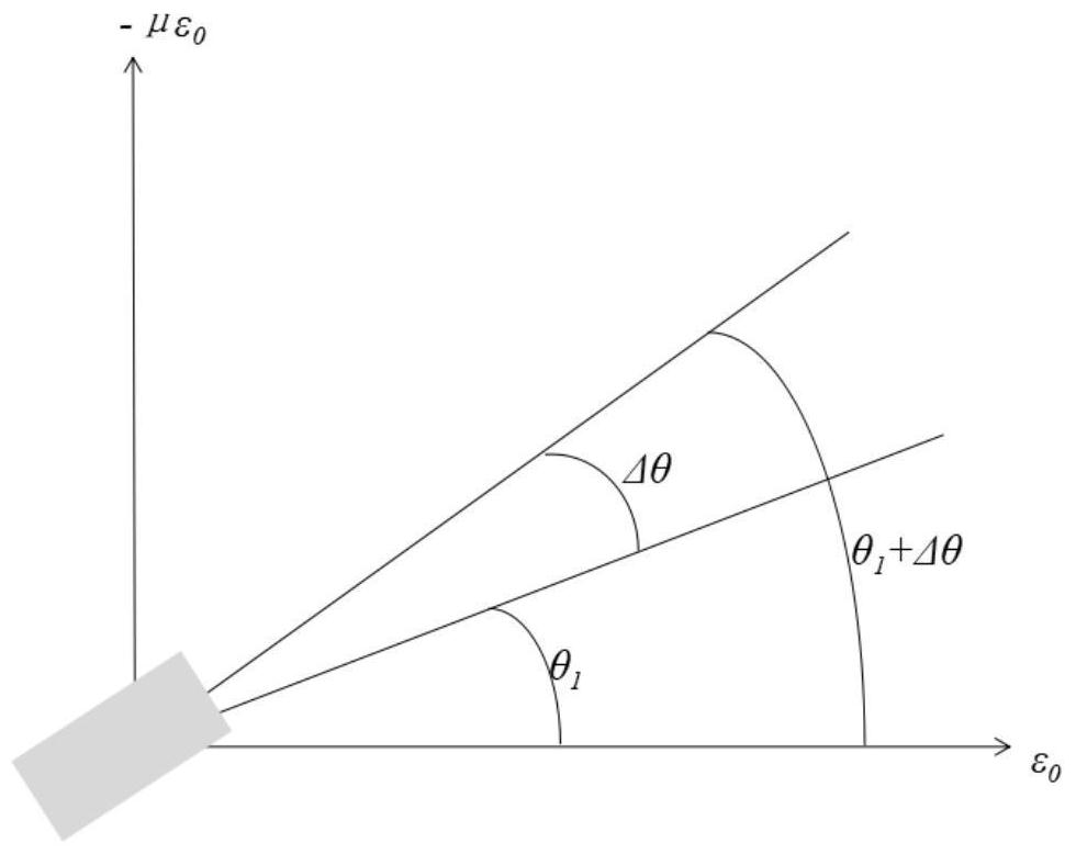
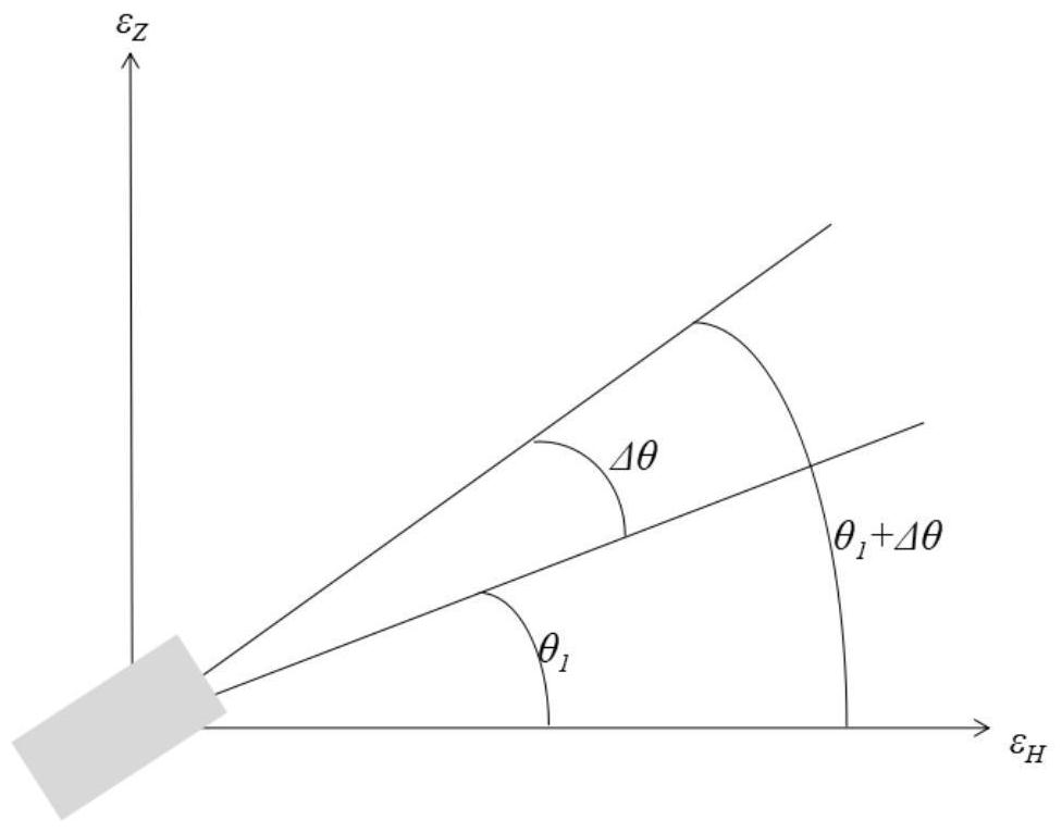
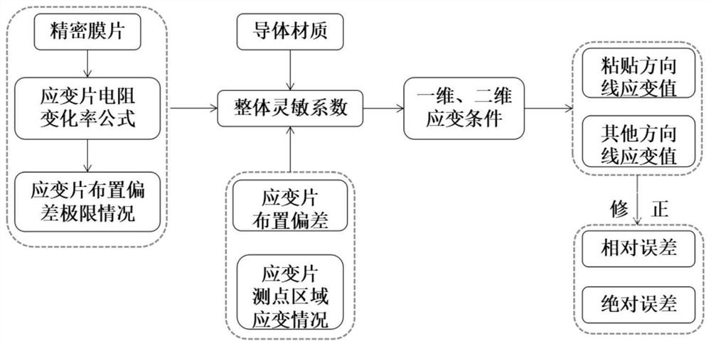
[0046] like Figure 1-3 As shown in the present invention, the principle of the strain value correction method in the case of deviation in the arrangement of precision diaphragm strain elements: by deriving the resistance change rate formula of the resistance strain gauge, the expression of the overall sensitivity coefficient of the strain gauge is obtained, and then based on the strain The element placement angle determines the correction method for the strain value.

[0047] In order to achieve the above purpose, the present invention provides a strain value correction method under the condition of deviation in the arrangement of precision diaphragm strain elements, such as: figure 1 , 2 , 3, the method includes the following steps:

[0048] 1) Express the resistance change rate of the resistance strain gauge in the form of formula (1), and formula (1) is:

[0049]

[0050] In formula (1), ΔR is the change value of the resistance, R is the initial value of the resistan...


PUM


Abstract

The invention provides a strain value correction method under the condition of arrangement deviation of a precise diaphragm strain element, and provides strain value correction methods under one-dimensional and two-dimensional deformation conditions respectively through deducing a resistance change rate formula of a resistance strain gauge to obtain an expression of an overall sensitivity coefficient of the strain gauge and through an arrangement deviation angle of the strain element. The method has the beneficial effects that the correlation between the strain measurement value of the precise diaphragm and the pasting angle of the strain gauge is considered, the strain value of the precise diaphragm under the condition of deviation of the strain element arranged on the precise diaphragm is corrected, and the precision of strain measurement by pasting the strain gauge on the precise diaphragm is improved. The improvement of the precision can improve the deformation measurement precision in a strain sensor and a precision structure test to the greatest extent, and the application of the strain sensor at an extreme temperature is served.

Description

technical field [0001] The invention belongs to the field of sensor science and technology, and particularly relates to a strain value correction method under the condition of deviation of arrangement of precision diaphragm strain elements. Background technique [0002] Resistive strain gauges are widely used in the mechanical properties testing of devices based on their good stability. The core of the resistance strain gauges is the sensitive grid in the strain gauges composed of conductor materials. The effect accumulates many small deformations generated in the testing process into a large deformation, thereby affecting the resistance value of the strain gauge, which can be intuitively measured by professional testing instruments. Through the calculation formula, the strain amount of the strain gauge can be inverted. [0003] Generally, the strain gauge can only measure the line strain or regional equivalent strain in a certain direction, that is, when using it, first st...

Claims


Application Information

Patent Timeline
Patent Type & Authority Applications(China)
IPC IPC(8): G01B7/16
CPCG01B21/045G01B7/18
Inventor 薛强罗睿陈之祥万勇陈新李江山
Owner INST OF ROCK & SOIL MECHANICS CHINESE ACAD OF SCI
Why Eureka
Try Eureka