Supercharge Your Innovation With Domain-Expert AI Agents!

Power-on detection device for brazing uniformity of LED wiring circuit board

A detection device and uniformity technology are applied in the field of energization detection devices for soldering uniformity of LED wiring circuit boards, which can solve the problems of low detection efficiency, accumulation of heat in solder joints, and the inability of energization detection devices to detect empty rooms, so as to improve the connection and disconnection. Sensitivity, the effect of improving conductivity

Active Publication Date: 2022-07-08
江苏锦花电子股份有限公司
View PDF7 Cites 1 Cited by
  • Summary
  • Abstract
  • Description
  • Claims
  • Application Information

AI Technical Summary

Problems solved by technology

[0004] Most of the current power-on detection devices can only detect the overall continuity of the LED wiring board, but cannot detect the welding quality of a single LED, and the detection efficiency is low
In addition, when the LED is soldered, it is easy to form a cavity at the solder joint, and the existing power-on detection device cannot detect the cavity. When the solder joint with the cavity is consistent with the normal solder joint resistance, it is easy Affect the detection accuracy. During the long-term use of the LED, the solder joints will accumulate heat, causing the gas inside the cavity to expand due to heat, deforming the solder joints, affecting the mechanical strength of the connection between the LED and the circuit board, and reducing the overall service life.

Method used


Image

  • Power-on detection device for brazing uniformity of LED wiring circuit board
  • Power-on detection device for brazing uniformity of LED wiring circuit board
  • Power-on detection device for brazing uniformity of LED wiring circuit board

Examples


Embodiment Construction

[0033] The technical solutions in the embodiments of the present invention will be clearly and completely described below with reference to the accompanying drawings in the embodiments of the present invention. Obviously, the described embodiments are only a part of the embodiments of the present invention, rather than all the embodiments. Based on the embodiments of the present invention, all other embodiments obtained by those of ordinary skill in the art without creative efforts shall fall within the protection scope of the present invention.

[0034] The present invention provides technical solutions:

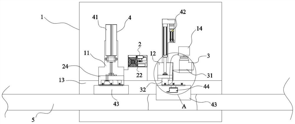
[0035] like Figure 1 to Figure 7 As shown in the figure, an LED wiring circuit board brazing uniformity energization detection device includes a detection box 1, an adjustment device 2, a diversion device 3, a support device 4 and a conveyor belt 5, and the detection box 1 is connected with the adjustment device 2. The adjustment device 2. It is electrically connected wit...


PUM


Abstract

The invention discloses an LED wiring circuit board brazing uniformity power-on detection device, which comprises a detection box, an adjusting device, a flow guide device, a supporting device and a conveying belt, and is characterized in that the detection box is connected with the adjusting device, the adjusting device is electrically connected with the flow guide device, the flow guide device is connected with the detection box, and the detection box is fixedly connected with the supporting device; the supporting device is in transmission connection with the adjusting device and the flow guiding device, the conveying belt is movably connected with the detection box and is in transmission connection with the supporting device, a working cavity is formed in the detection box, a feeding port and a discharging port are formed in the two ends of the working cavity respectively, one end of the conveying belt sequentially penetrates through the feeding port, the working cavity and the discharging port, and circuit boards are conveyed through the conveying belt. The adjusting device and the flow guiding device are driven by the supporting device, so that continuous detection is carried out, movement interference is prevented, power is provided for the two ends of the inner ring of the conveying belt through the power roller, and continuous conveying is automatically carried out.

Description

technical field [0001] The invention relates to the technical field of soldering uniformity detection of LED circuit boards, in particular to a power-on detection device for soldering uniformity of LED wiring circuit boards. Background technique [0002] In recent years, with the continuous upgrading of smart devices, the requirements for the LED processing technology that play a role in display are getting higher and higher. The LED is soldered on the circuit board through the brazing process to facilitate accurate display. [0003] The circuit board, as the carrying part of the LED, is subject to high temperature during the welding process. The melted solder will weld the LED on the surface of the circuit board. However, the qualification of the welding process is not well controlled. Soldering or virtual welding will affect the uniformity of the power supply. Over-soldering may easily cause partial circuit breakage of the circuit board, while virtual welding may easily le...

Claims


Application Information

Patent Timeline
IPC IPC(8): G01R31/28
CPCG01R31/2806G01R31/281
Inventor 叶金华
Owner 江苏锦花电子股份有限公司
Features
  • R&D
  • Intellectual Property
  • Life Sciences
  • Materials
  • Tech Scout
  • Unparalleled Data Quality
  • Higher Quality Content
  • 60% Fewer Hallucinations
Learn More