Universal actuator, camera module and terminal equipment
An actuator and motion technology, applied in the field of camera modules, terminal equipment, and universal actuators, can solve the problems of a large number and complex structure of the driving mechanism, and achieve the effect of a simple structure
- Summary
- Abstract
- Description
- Claims
- Application Information
AI Technical Summary
Problems solved by technology
Method used
Image
Examples
no. 1 example
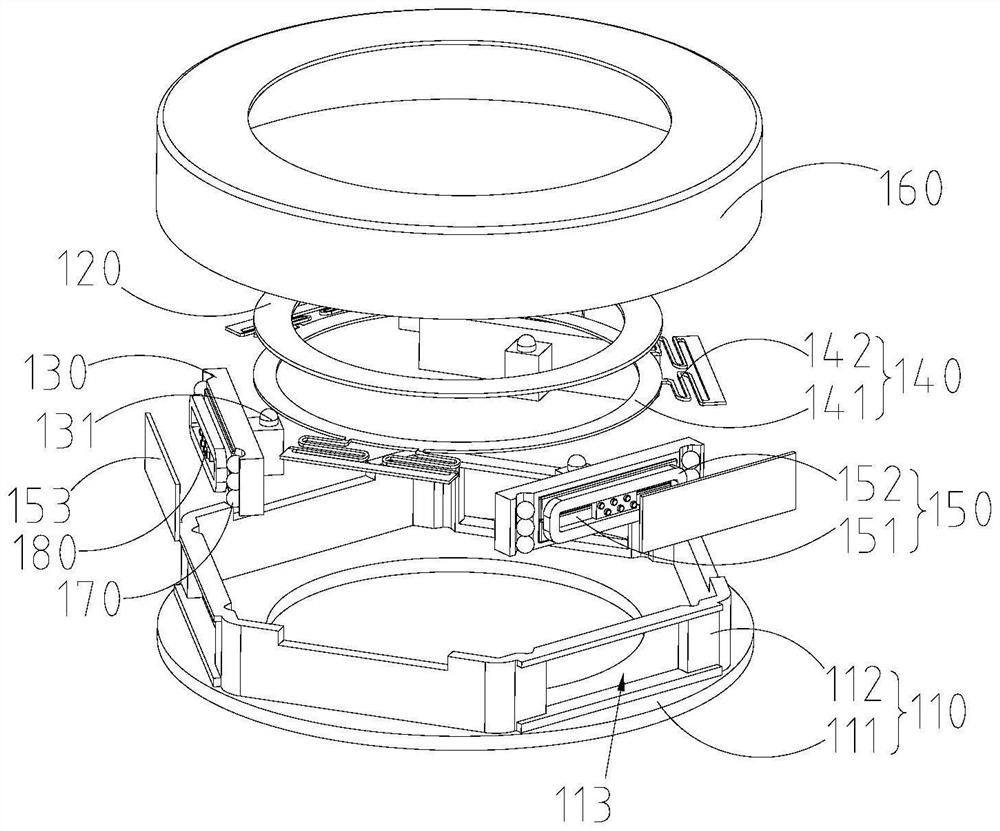
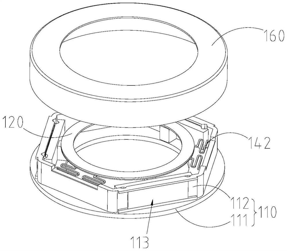
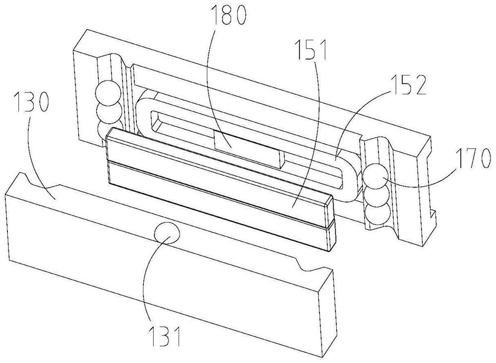
[0045] refer to Figure 1-Figure 2 , to provide a universal actuator, including: a base 110, a platform 120 and three supports 130, wherein, the base 110 includes a ring-shaped bottom plate 111 and a plurality of elongated vertical bars standing between the inner circumference and the outer circumference of the bottom plate 111 For the plate 112, a plurality of vertical plates 112 are connected end to end to form a polygon, for example, the polygon can be inscribed with the outer circumference of the circular bottom plate 111. Here, in this embodiment, the bottom plate 111 may be configured as a circular ring, and in some other embodiments, the bottom plate 111 may be configured as a square ring.
[0046] Further, in this embodiment, the number of vertical plates 112 may be six, of course, in other embodiments, the number of vertical plates may be other numbers, such as eight, nine and so on. In addition, in some other embodiments, the bottom plate 111 may also be configured ...
no. 2 example
[0059] refer to Image 6 and Figure 7 , this embodiment provides a universal actuator, which is different from the first embodiment in that, in this embodiment, in order to allow the platform 220 to press the supporting member 230, the elastic sheet 290 is used instead of the first embodiment. For the elastic member 142 , the restoring force is completely realized by the cooperation of the magnetic conductive sheet 253 and the magnet 251 . For the structure of other parts, reference may be made to the first embodiment, which will not be repeated here.
[0060]In this embodiment, in order to enable the platform 220 to be pressed against the support member 230 , the universal actuator further includes an elastic piece 290 , one end of which is fixed to the platform 220 and the other end to the support member 230 . The elastic piece 290 has the function of pressing the platform 220 . Tighten the elastic force of the protrusion 231 . At this time, one end of the elastic sheet ...
no. 3 example
[0066] refer to Figure 8 , this embodiment provides a universal actuator. The difference from the first embodiment is that in this embodiment, the driving mechanism 350 is replaced by an SMA driver instead of an electromagnetic driver, and the structure of the platform 320 is adaptively adjusted. The bearing mode of the 320 is completed by the bearing portion 341, and the design of the support member is cancelled, and the structure of other parts can be referred to the first embodiment for details, which will not be repeated here.
[0067] In this embodiment, the platform 320 may be configured as a stepped shaft, that is, the outer peripheral surface of the platform 320 has a large diameter section 321 and a small diameter section 322, wherein the large diameter section 321 is located away from the base 310, that is, the small diameter section 322 is close to the base 310 is arranged to form a stepped surface toward the base 310 . Of course, in this embodiment, the platform ...
PUM
 Abstract
Description
Claims
Application Information
 - R&D
- Intellectual Property
- Life Sciences
- Materials
- Tech Scout
- Unparalleled Data Quality
- Higher Quality Content
- 60% Fewer Hallucinations
Browse by: Latest US Patents, China's latest patents, Technical Efficacy Thesaurus, Application Domain, Technology Topic, Popular Technical Reports.
© 2025 PatSnap. All rights reserved.Legal|Privacy policy|Modern Slavery Act Transparency Statement|Sitemap|About US| Contact US: help@patsnap.com


