Numerical control machine for lapping spiral bevel gear

A technology of spiral bevel gears and gear grinding machines, which is applied to belts/chains/gears, gear teeth, mechanical equipment, etc., can solve the problems of easy failure, complex machine tool structure, low degree of automation, etc., to maintain dynamic stability. , The compact structure of the machine tool and the effect of improving production efficiency

Active Publication Date: 2009-04-15
通用技术集团天津第一机床有限公司
View PDF0 Cites 5 Cited by
  • Summary
  • Abstract
  • Description
  • Claims
  • Application Information

AI Technical Summary

Problems solved by technology

[0004] The above-mentioned prior art spiral bevel gear grinding machine has the following defects: 1. The machine tool has a complex structure, many parts, difficult manufacturing and assembly, difficult adjustment, and prone to failure
2. The gear installation distance is manually adjusted, and the error is large
3. Belt drive, large and small wheel spindles have lost rotation, and the reaction torque is not accurate, which affects the processing quality 4. Low degree of automation and low efficiency
5. High labor intensity

Method used


Image

  • Numerical control machine for lapping spiral bevel gear
  • Numerical control machine for lapping spiral bevel gear
  • Numerical control machine for lapping spiral bevel gear

Examples


Embodiment Construction

[0057] Embodiments of the present invention will be further described below in conjunction with the accompanying drawings.

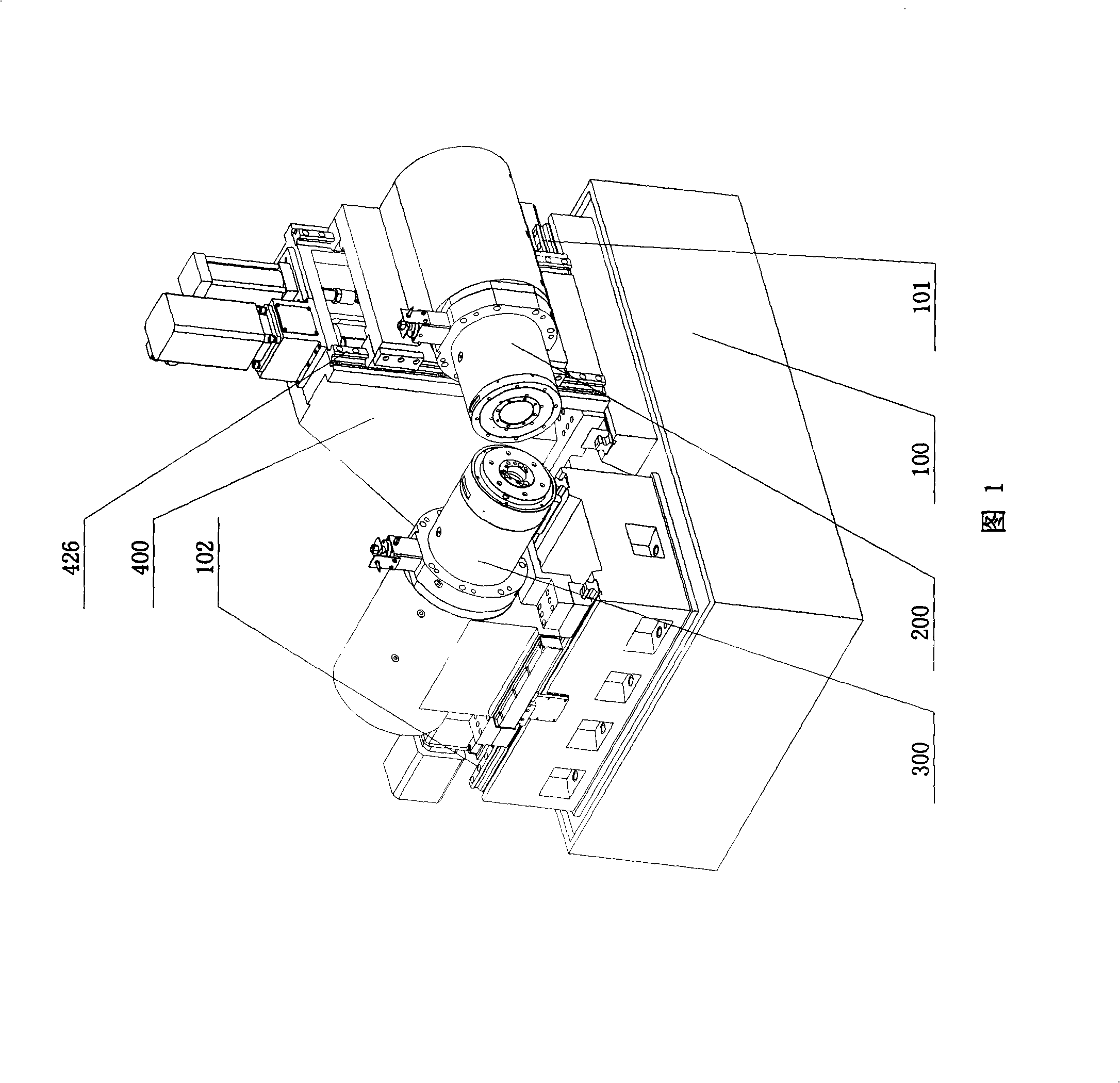
[0058] As shown in Figure 1, the present invention provides a CNC spiral bevel gear grinding machine, the CNC bevel gear grinding machine includes: a bed 100, a column 400, a driving box 200, a driven box 300, a numerical control system (not shown in the figure) shown); on the bed 100, a driving guide rail 101 and a driven guide rail 102 which are 90° to each other are arranged.

[0059]The column 400 is arranged on the active guide rail 101 on the bed 100, and an automatic movement mechanism that moves along the active guide rail 101 is arranged between the bottom of the column 400 and the bed 100; the active box 200 is hung on the side of the column 400, and the active box The bottom of the 200 is provided with an automatic movement mechanism that can move vertically along the side of the column 400; the driven box 300 is arranged on the driven guide r...


PUM


Abstract

The invention discloses a numerical control spiral bevel gear lapping machine, which comprises a bed piece, an upright post, a driving headstock, a driven headstock, and a numerical control system, wherein the bed piece is provided with a driving guide rail and a driven guide rail, the upright post is arranged on the driving guide rail, and an automatic moving mechanism is arranged between the bottom of the upright post and the bed piece; the driving headstock is laterally suspended at the side surface of the upright post, and the bottom of the driving headstock is provided with an automatic moving mechanism; the driven headstock is arranged on the driven guide rail on the bed piece, and an automatic moving mechanism is arranged between the bottom of the driven headstock and the bed piece; the driving headstock and the driven headstock are provided with a driving spindle and a driven spindle respectively, and inner holes of the driving spindle and the driven spindle are provided with a driving gear and a driven gear respectively. The numerical control spiral bevel gear lapping machine has the advantages that the numerical control spiral bevel gear lapping machine has a compact structure, ensures that an operator can furthest approach workpieces, automatically recognizes teeth and adjusts the mounting distance and the side clearance of a bevel gear pair, adopts an electric spindle technology to realize the zero transmission of the revolution of the two spindles and improve the speed and maintain the dynamic stability at high speed, and has high production efficiency.

Description

technical field [0001] The invention relates to a numerically controlled bevel gear grinding machine, in particular to a numerically controlled spiral bevel gear grinding machine. Background technique [0002] The CNC spiral bevel gear grinding machine is used for high-speed and precise grinding of spiral bevel gears and hypoid gears. Its purpose is to correct the deformation of the gear heat treatment, improve the tooth surface finish, improve the position and size of the contact area, and achieve stable transmission. Reduce noise and improve carrying capacity. The processing method is to install a pair of bevel gears on the two corresponding main shafts of the gear grinding machine, and maintain a certain side clearance, and at the same time grind the large and small wheels in the axial direction and offset distance. ~50Nm braking torque, and add a certain flow rate and pressure of grinding fluid to the meshing point of the two wheels, and grind until the tooth surface tu...

Claims


Application Information

Patent Timeline
Patent Type & Authority Applications(China)
IPC IPC(8): B23F19/02B23Q1/01B23Q1/44B23B19/02
Inventor 沈凤美柴宝连王威
Owner 通用技术集团天津第一机床有限公司
Why Eureka
Try Eureka