
Diaphragm-type pneumatic proportional pressure reducing valve of edge cam driven by servo motor directly

A technology of servo motor and end face cam, which is applied in the direction of lifting valve, valve detail, safety valve, etc., can solve the problems of poor linearity, high cost, poor oil and water pollution ability, etc., and achieve improved dynamic performance, compact structure, and precision Adjustment effect

Inactive Publication Date: 2014-07-16
XI AN JIAOTONG UNIV
View PDF5 Cites 4 Cited by
  • Summary
  • Abstract
  • Description
  • Claims
  • Application Information

AI Technical Summary

Problems solved by technology

However, the traditional electrical proportional pressure valves currently used in industrial practice often use specially designed DC proportional electromagnets to adjust the valve output pressure. This traditional proportional valve has high cost, poor dynamic and static performance, and has a certain degree of insensitivity. Zone and hysteresis, and poor linearity, poor resistance to oil and water pollution in compressed air, and low resistance to vibration and shock in machine tool use

Method used


Image

  • Diaphragm-type pneumatic proportional pressure reducing valve of edge cam driven by servo motor directly
  • Diaphragm-type pneumatic proportional pressure reducing valve of edge cam driven by servo motor directly

Examples


Embodiment Construction

[0012] The present invention will be further described in detail below in conjunction with the accompanying drawings.

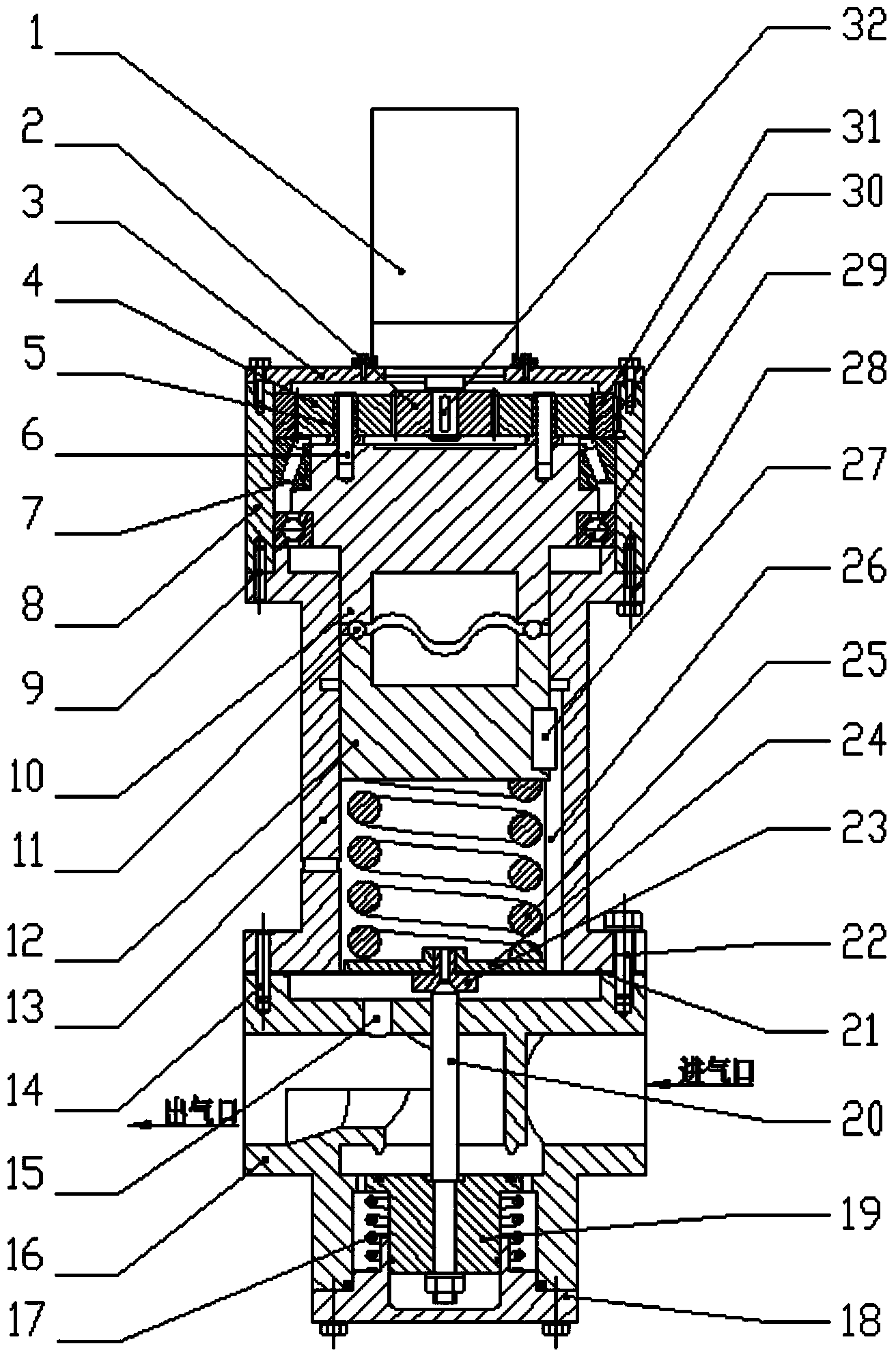
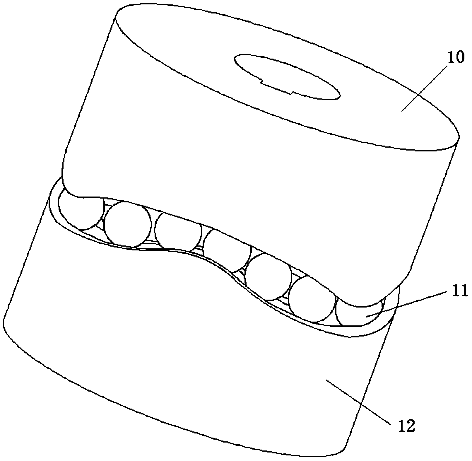
[0013] refer to figure 1 , a diaphragm type pneumatic proportional pressure reducing valve directly driven by a servo motor, including a casing 8, the servo motor 1 is fixed on the upper end cover 3 connected to the top of the casing 8, the output shaft of the servo motor 1 is connected to the sun gear of the planetary reducer 2 Through the clearance fit of the first key 32, the planetary gear 4 of the planetary reducer is connected to the upper end cam 10 through the bushing 5 and the pin shaft 6, driving the upper end cam 10 to rotate, and the outer ring and inner ring of the tapered roller bearing 7 are respectively formed by The ring gear 31 and the upper end face cam 10 are positioned, the outer ring and the inner ring of the deep groove ball bearing 29 are respectively positioned by the upper valve body 13 and the upper end face cam 10, and the upper pa...


PUM


Abstract

The invention provides a diaphragm-type pneumatic proportional pressure reducing valve of an edge cam driven by a servo motor directly. An output shaft of the serve motor is in clearance fit with a sun gear of a planetary reducer, a planet gear of the planetary reducer is connected with an upper edge cam body, the upper edge cam body is matched with a lower edge cam body, the lower portion of the lower edge cam body is connected with a pressure adjusting spring, the lower end of the pressure adjusting spring is connected onto a spring end cover, a diaphragm is fixed between an upper valve body and a lower valve body in a compressed mode and located on the lower portion of the spring end cover, an overflow valve is installed in the middle of the spring end cover, a valve rod penetrates through the diaphragm to butt against a valve port of the overflow valve, the lower end of the valve rod is connected with a valve element, an air inlet and an air outlet are formed in the two sides of a lower valve body, an air feedback hole is formed in the lower valve body, the outer portion of the valve element is connected with a reset spring, and the valve element, the reset spring and a lower end cover are connected in a sealed mode. The servo motor directly drives the edge cam to compress the springs so as to achieve linear motion of the valve element, the structure is compact, transmission is stable, and dynamic control can be achieved.

Description

technical field [0001] The invention belongs to the technical field of pneumatic proportional pressure reducing valves, in particular to a diaphragm type pneumatic proportional pressure reducing valve directly driven by a servo motor. Background technique [0002] The pressure reducing valve is a pressure control valve that reduces the inlet pressure to a certain outlet pressure by changing the throttling area to cause a pressure drop when the fluid passes through, and relies on the energy of the medium itself to keep the outlet pressure automatically stable. According to the control pressure, traditional pressure reducing valves can be divided into three types: fixed value, constant ratio and fixed difference. According to the structure and working principle, it can be divided into two types: direct acting pressure reducing and overflow valve and pilot pressure reducing valve. They are all mechanical manual pressure regulating valves, and the adjustment accuracy is not high...

Claims


Application Information

Patent Timeline
Patent Type & Authority Applications(China)
IPC IPC(8): F16K17/04F16K31/04
CPCF16K1/00F16K31/047F16K31/52408F16K31/53
Inventor 赵升吨金立波李靖祥张宗元
Owner XI AN JIAOTONG UNIV
Learn More