Gas soot blower

A soot blower and gas technology, applied in the field of gas soot blowers, can solve the problems of soot blowing dead angle and poor soot blowing effect, and achieve the effect of eliminating soot blowing dead angle, improving soot blowing effect and improving soot blowing area

Inactive Publication Date: 2013-06-12
CHINA PETROLEUM & CHEM CORP +1
View PDF2 Cites 5 Cited by
  • Summary
  • Abstract
  • Description
  • Claims
  • Application Information

AI Technical Summary

Problems solved by technology

[0004] What the present invention aims to solve is the technical problem that the existi

Method used


Image

  • Gas soot blower

Examples


Embodiment Construction

[0010] The present invention will be further described in detail below in conjunction with the accompanying drawings and specific embodiments. The drawings and specific embodiments do not limit the scope of protection claimed by the present invention.

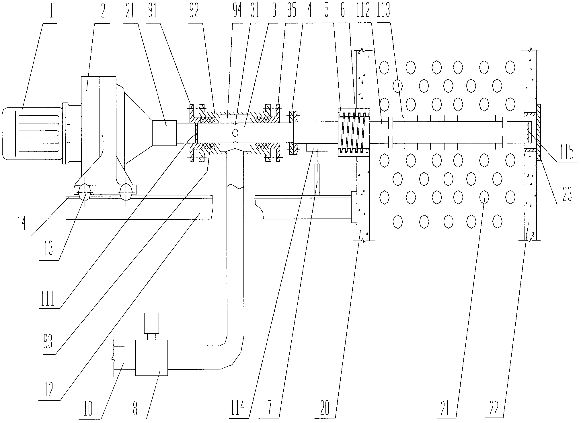
[0011] figure 1 It is a specific embodiment of the gas soot blower used in the tubular heating furnace of the present invention. It is equipped with a transmission system, an air intake system, a limit system, a feed system, a soot blowing tube assembly, and a bracket 12 . The transmission system is provided with a motor 1, a reducer 2, a shaft coupling 21, and a pulley 13. The reducer 2 of the soot blower is a cycloid reducer, which can be various commonly used types in industry. The present invention adopts the cycloid reducer, because its deceleration ratio is relatively large (can reach 700~1500).

[0012] The feeding system of the soot blower is a lead screw and nut auxiliary mechanism, which is provided with a hollow le...


PUM


Abstract

The invention provides a gas soot blower which comprises a transmission system, a gas inlet system, a limit system, a feed system, a soot blowing pipe component and a bracket, wherein the limit system comprises a collision block and a limit switch; the feed system is a lead screw nut pair mechanism and comprises a hollow lead screw and a nut; one end of a gas inlet pipe of the gas inlet system is connected with a coupler of the transmission system, and the other end of the gas inlet pipe of the gas inlet system is connected with one end of the soot blowing pipe; the collision block is arranged on the soot blowing pipe and matched with the limit switch arranged on the bracket to jointly form the limit system; and the hollow lead screw is sleeved on the soot blowing pipe, welded into a whole with the soot blowing pipe and matched with the nut on a front furnace wall to form the lead screw nut pair mechanism. According to the gas soot blower provided by the invention, through the actions of the limit system and the feed system, the rotations of a motor are converted into rotary motions and reciprocating linear motions of a soot blowing nozzle, so that the stretching of the soot blowing nozzle is realized, a soot blowing area of the soot blowing nozzle is greatly enlarged, and soot blowing dead angles are eliminated.

Description

technical field [0001] The invention relates to a gas soot blower used in tubular heating furnaces in petroleum refining and petrochemical fields. Background technique [0002] With the change of crude oil properties and the increase of sulfur content, the problem of fouling and fouling on the convection section and the heating surface of the preheating section of domestic petrochemical enterprises is becoming more and more serious. Once the heating surface accumulates dust, it will seriously affect the heat transfer effect of the heating surface. In the case of serious ash in the convective area, the heat transfer capacity will be reduced by about 30% to 50%, which will reduce the thermal efficiency of the heating furnace by more than 5%, and the fuel energy consumption of the heating furnace accounts for 30% to 40% of the total energy consumption of the refinery. %, so the dust accumulation in the convection section of the domestic petrochemical heating furnace increases ...

Claims


Application Information

Patent Timeline
IPC IPC(8): F23J3/02
Inventor 郜建松孙志钦孟庆凯
Owner CHINA PETROLEUM & CHEM CORP
Why Eureka
Try Eureka