Clutch for rail vehicle

A rail vehicle and clutch technology, applied in the field of rail vehicle clutches, can solve the problems of type and mode control, insufficient accuracy, damage, etc.

Pending Publication Date: 2022-07-08
KWD KUPPLUNGSWERK DRESDEN
View PDF4 Cites 0 Cited by
  • Summary
  • Abstract
  • Description
  • Claims
  • Application Information

AI Technical Summary

Problems solved by technology

[0008] A disadvantage of the solutions known from the prior art is that the assembly and disassembly of such a clutch is complicated and damage occurs during assembly when the clutch halves to be engaged are brought together
Furthermore, the solutions known from the prior art only enable insufficient precision when assembling the clutch
According to the prior art, it is not possible to control the correct and positionally precise assembly in a simple type and manner

Method used


Image

  • Clutch for rail vehicle
  • Clutch for rail vehicle
  • Clutch for rail vehicle

Examples


Embodiment 1

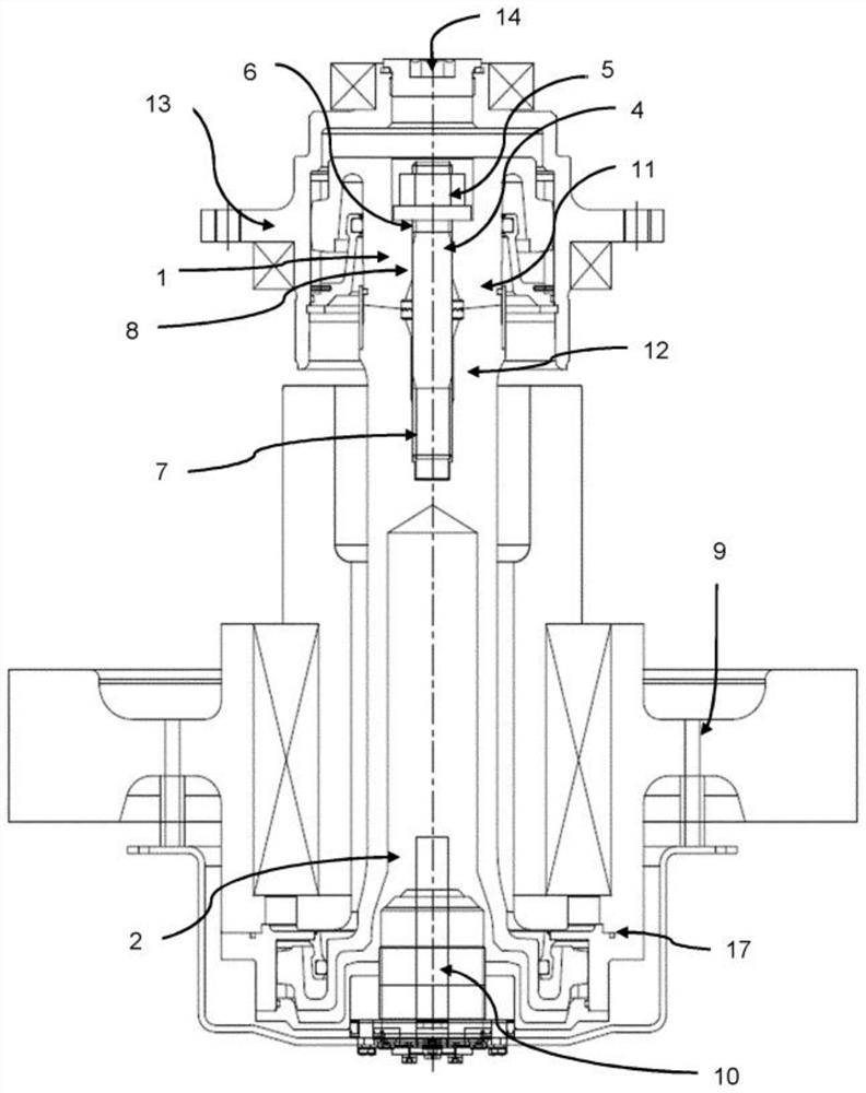
[0054] according to figure 1 A wheel drive with a two-piece clutch system for a rail vehicle is shown.

[0055] here, figure 1 The first clutch half 1 is shown, which is configured as a dog clutch and is connected to a gearbox (not shown) via the teeth of the drive-side sleeve 13 . The first clutch half 1 has a first clutch shaft 11 into which the through hole 8 is introduced centrally and axially. The first clutch shaft 11 is arranged in axial alignment with the second clutch shaft 12 . The second clutch shaft 12 is a component of the second clutch half 2 and has a central axially arranged set screw 4 on the end region side, which is screwed into the second clutch shaft 12 via the internal thread 7 of the set screw 4 . At the other end of the set screw 4 there is an external thread 6 onto which the nut 5 is screwed and thus the two clutch halves 1 and 2 are connected non-positively.

[0056] The grounding element 10 is connected not only to the second clutch half 2 but al...

Embodiment 2

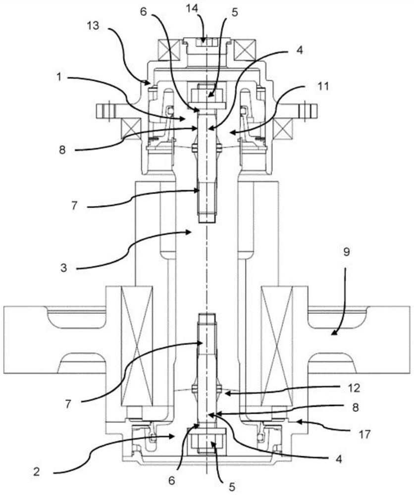
[0060] according to figure 2 , 3 and 4 show a wheel drive with a three-piece clutch system for rail vehicles.

[0061] here, figure 2 A clutch system with a clutch half 1 configured as a dog clutch is shown, wherein the dog clutch engages with a gearbox (not shown) and with the gears on the end side of the transmission shaft 3 . The first clutch half 1 has a first clutch shaft 11 into which the through hole 8 is introduced centrally and axially. The first clutch shaft 11 is arranged in axial alignment with the transmission shaft 3 and the second clutch shaft 12 .

[0062] At its left end, the transmission shaft 3 has a central axially arranged set screw 4 , which is screwed into the transmission shaft 3 via an internal thread 7 of the set screw 4 . At the other end of the set screw 4 there is an external thread 6 onto which the nut 5 is screwed and thus the transmission shaft 3 and the first clutch half 1 are connected in a non-positive manner.

[0063] At its right end...

Embodiment 3

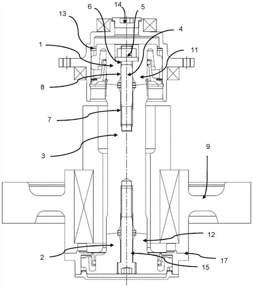
[0071] Figure 5 A three-part clutch system is shown in which the set bolt 4 is pre-assembled centrally and axially in the second clutch half 2 assigned to the wheel. In this case, the set screw 4 extends through the through hole 8 of the aligned transmission shaft 3 and further through the through hole 8 assigned to the first clutch half 1 of the drive. The end of the set screw protrudes from the first clutch half 1 , wherein the non-positive connection of the first clutch half 1 , the transmission shaft 3 and the second clutch half 2 is by means of a nut screwed on the external thread 6 of the set screw 4 5 to achieve.

[0072] Assembly of the clutch is carried out in such a way that the set screw 4 is pre-assembled into the clutch shaft 12 in the second clutch half 2 assigned to the wheel. The transmission shaft 3 with the through hole 8 is then pushed onto the set screw 4 and then the first clutch half 1 with the through hole 8 assigned to the drive is also pushed onto t...


PUM


Abstract

The invention relates to the field of rail vehicles, and relates to a dual-joint-acting clutch for compensating for axial, radial and angular offsets between a gearbox and a wheel. The aim of the invention is to provide an at least two-part clutch for a rail vehicle, which clutch is simple and safe during assembly, largely avoids damage during assembly of the clutch, and has a high-precision positioning of the engaged clutch halves. According to the invention, a clutch for a rail vehicle is provided, which clutch is a two-part and/or three-part clutch system, according to the invention, a pre-assembled positioning bolt, which is arranged axially centrally in the second clutch shaft, is present at least for aligning, centering, guiding and checking the second clutch half relative to the first clutch half, the positioning bolt protrudes from the first clutch half on the side facing away from the end face of the first clutch shaft by a region, by means of which at least one force-fitting connection of the first clutch half and the second clutch half is achieved.

Description

technical field [0001] The present invention relates to the field of rail vehicle technology and to a clutch for rail vehicles. The clutch according to the invention can be used in particular for rail vehicles with a double cardan-acting clutch to compensate for axial, radial and angular offsets between the gearbox and the wheels. Background technique [0002] Known clutches for rail vehicles are used as transmission means to transmit torque from the motor shaft to the wheels of the rail vehicle via a gearbox and a clutch arranged downstream and connected to the gearbox and the wheels. [0003] Various solutions for such clutches are known from the prior art. [0004] EP 1 940 667 A1 discloses a double universal joint clutch with two joint planes for rail vehicles, which comprises two clutch joints and is surrounded by a hollow pinion shaft for torque transmission via a hollow pinion shaft The shafts are connected to each other. One joint plane is assigned to the clutch j...

Claims


Application Information

Patent Timeline
Patent Type & Authority Applications(China)
IPC IPC(8): B61C9/44
CPCB61C9/44
Inventor T·汉奈尔N·费希尔
Owner KWD KUPPLUNGSWERK DRESDEN
Why Eureka
Try Eureka