Light control device and lighting device

A technology for light control and electrode control, which is applied to lighting devices, lighting device parts, lighting and heating equipment, etc., can solve problems such as electric field disturbance, and achieve the effect of reducing ineffective areas

Pending Publication Date: 2022-07-08
JAPAN DISPLAY INC
View PDF8 Cites 0 Cited by
  • Summary
  • Abstract
  • Description
  • Claims
  • Application Information

AI Technical Summary

Problems solved by technology

The lead-out electrode connected to each strip electrode is provided in the effective area where the liquid crystal lens is formed, and it may become a factor that disturbs the electric field used to form the liquid crystal lens

Method used


Image

  • Light control device and lighting device
  • Light control device and lighting device
  • Light control device and lighting device

Examples


Embodiment Construction

[0032] Hereinafter, the present embodiment will be described with reference to the drawings. In addition, the disclosure is only an example after all, and it is a matter of course that appropriate changes that can be easily conceived by those skilled in the art without changing the gist of the invention are included in the scope of the present invention. In addition, in the drawings, in order to clarify the description, the width, thickness, shape, etc. of each part may be schematically shown compared with the actual form, but this is only an example in the end, and does not apply to the present invention. The interpretation of the invention constitutes a limitation. In addition, in this specification and each of the drawings, components that perform the same or similar functions as components described in the previous drawings may be denoted by the same reference numerals, and overlapping detailed descriptions may be appropriately omitted. .

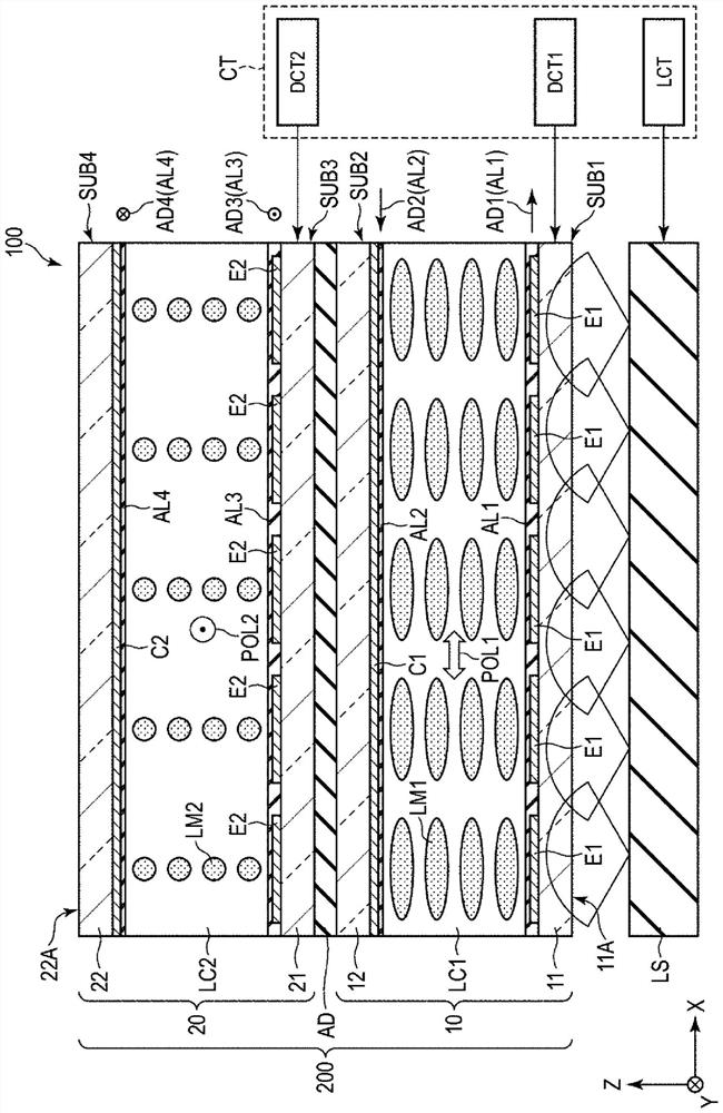
[0033] figure 1 It is a figur...


PUM


Abstract

The purpose of the present embodiment is to provide a light control device and a lighting device capable of reducing an ineffective area. A light control device according to an embodiment includes: a first substrate including a plurality of first control electrodes provided in an effective region and a plurality of power supply lines provided in a peripheral region; a second substrate; and a first liquid crystal layer held between the first substrate and the second substrate, the first control electrode is a transparent electrode and includes, in the effective region, a first section intersecting a first direction at a first angle, a second section intersecting the first direction at a second angle, and a third section intersecting the first direction at a third angle. The first control electrode extends and protrudes toward the peripheral region and is electrically connected to the power supply line, and the first to third angles are different from each other.

Description

technical field [0001] Embodiments of the present invention relate to a light control device and a lighting device. Background technique [0002] In recent years, various liquid crystal lenses for controlling the path of light emitted from a light source have been proposed. In one example, a liquid crystal lens including a plurality of arc electrodes and extraction electrodes connected to the arc electrodes is disclosed. In another example, a plurality of liquid crystal lenses are superimposed, and the strip electrodes of one liquid crystal lens overlap with the strip electrodes of the other liquid crystal lens in an offset manner, and a technique of finely arranging the strip electrodes is known. The extraction electrodes connected to the respective strip electrodes are provided in the effective area for forming the liquid crystal lens, and may be a factor that disturbs the electric field for forming the liquid crystal lens. [0003] prior art literature [0004] Patent ...

Claims


Application Information

Patent Timeline
Patent Type & Authority Applications(China)
IPC IPC(8): G02F1/13
CPCG02F1/1343G02F1/13G02F1/1347G02F1/1345G02F1/29G02F2202/28G02F1/134309G02F1/13471
Inventor 小系健夫三井雅志黑川多惠
Owner JAPAN DISPLAY INC
Why Eureka
Try Eureka