Medical infusion heating device

A technology of a heating device and a heating mechanism, which is applied in the direction of devices introduced into the body, hypodermic injection devices, etc., can solve the problems of patients' physical discomfort and inability to heat medicinal liquid, and achieve the effect of solving physical discomfort and preventing heat loss.

Pending Publication Date: 2022-07-12
康志华
View PDF1 Cites 0 Cited by
  • Summary
  • Abstract
  • Description
  • Claims
  • Application Information

AI Technical Summary

Problems solved by technology

[0005] In order to overcome the disadvantage that the above-mentioned patent only indirectly heats the arm of the patient for infusion, and cannot directly heat the medicinal solution, causing the patient to feel uncomfortable when the patient is infused with cold medicinal solution. The purpose of the present invention is to provide A medical infusion heating device capable of heating medicinal fluid input by a patient

Method used


Image

  • Medical infusion heating device
  • Medical infusion heating device
  • Medical infusion heating device

Examples


Embodiment 1

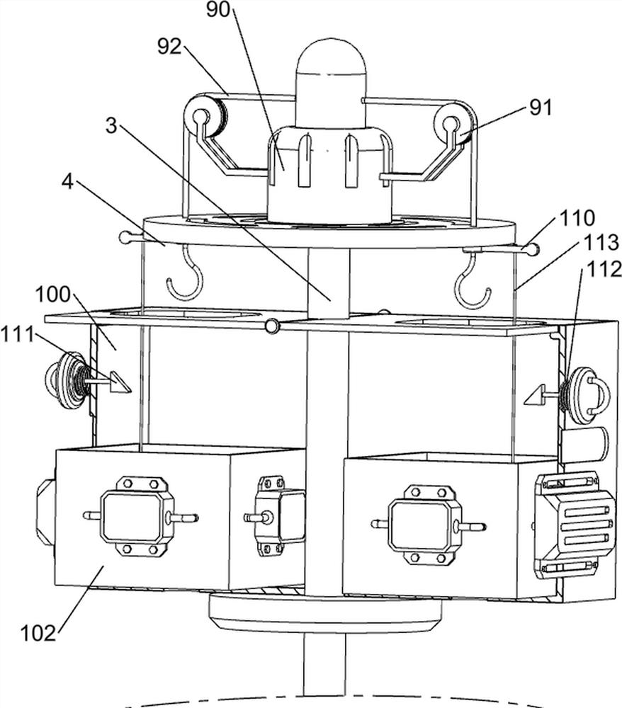
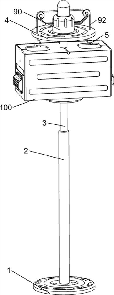
[0075] A medical infusion heating device, such as Figure 1-Figure 10 As shown, it includes a support base 1, a sleeve 2, a lifting rod 3, a support plate 4, a hook 5, a clamping rod 6, a support plate 7, a return spring 8, a pulling mechanism 9, a heating mechanism 10 and a limit mechanism 11. There is a sleeve 2 in the middle of the top of the seat 1. Six positioning holes are evenly spaced on the front and rear sides of the inner wall of the sleeve 2. A lift rod 3 is slidably arranged in the sleeve 2. The upper part of the lift rod 3 is provided with a support plate 4. The support plate 4. Hooks 5 are slidably provided on the front and rear sides of the bottom, and clamping rods 6 are slidably provided on both the front and rear sides of the lift rod 3. The two clamping rods 6 are in contact with the sleeve 2, and the inner sides of the two clamping rods 6 are provided with Support plate 7, the two support plates 7 are slidably connected with the lift rod 3, a return spring...

Embodiment 2

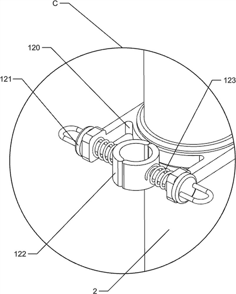
[0081] On the basis of Example 1, as figure 1 , Figure 11 and Figure 12 As shown, it also includes a clamping mechanism 12. The clamping mechanism 12 includes a sliding ring 120, a pull rod 121, a clamping ring 122 and a compression spring 123. The upper part of the sleeve 2 is slidably provided with a sliding ring 120. There are tie rods 121 symmetrically sliding on the sides. There are four tie rods 121. The inner sides of the four tie rods 121 are provided with clamping rings 122. The two adjacent clamping rings 122 are in contact. There are compression springs 123 between them.

[0082] When the patient is undergoing infusion, in order to prevent the infusion tube from moving freely and affecting the patient's infusion, people move the sliding ring 120 along the sleeve 2 to move the sliding ring 120 to a suitable position, and then pull the pull rod 121 along the sleeve 2. The sliding ring 120 moves to the outside, the pull rod 121 drives the clamp ring 122 to move to...


PUM


Abstract

The invention relates to a heating device, in particular to a medical infusion heating device. The invention provides a medical infusion heating device capable of heating liquid medicine infused by a patient. A medical infusion heating device comprises a sleeve arranged in the middle of the top of a supporting seat; the lifting rod is arranged in the sleeve in a sliding manner; the supporting disc is arranged at the upper part of the lifting rod; the hooks are arranged on the front side and the rear side of the bottom of the supporting disc in a sliding mode; the clamping rods are arranged on the front side and the rear side in the lifting rod in a sliding mode, and the two clamping rods make contact with the sleeve. The lifting rod is pulled by people to move along the sleeve, and after the lifting rod is adjusted to the height suitable for a patient, the clamping rod moves outwards to be in contact with the positioning hole in the inner wall of the sleeve, so that the clamping rod is clamped by the sleeve, the lifting rod is not prone to moving at will, and adjustment can be conducted according to the infusion height needed by the patient.

Description

technical field [0001] The invention relates to a heating device, in particular to a medical infusion heating device. Background technique [0002] Intravenous infusion is one of the most common drug delivery methods in medical treatment. Since the temperature of the infused liquid is mostly lower than that of the human body, the existing ordinary infusion devices do not have any heating measures. Therefore, when the infusion fluid enters the vein, people will feel cold, and the long-term infusion will make the patient feel uncomfortable, with acupuncture pain, which can cause hypothermia, chills and other uncomfortable symptoms in the patient. [0003] Patent application CN213131348U, published on 20210507, discloses a medical infusion heating device, comprising a rectangular bottom plate, a chamber is provided on the lower bottom surface of the bottom plate, a controller is provided in the chamber, and a connection block is provided on the upper surface of the bottom plate...

Claims


Application Information

Patent Timeline
Patent Type & Authority Applications(China)
IPC IPC(8): A61M5/44A61M5/14
CPCA61M5/445A61M5/1415A61M5/1417
Inventor 康志华
Owner 康志华
Why Eureka
Try Eureka