Water and fertilizer flow regulating valve and regulating method

A flow regulating valve, water and fertilizer technology, applied in the direction of valve device, valve details, sliding valve, etc., can solve the problems of unsuitable water and fertilizer use environment, complex structure, many internal compartments, etc., to reduce control complexity, convenient operation, The effect of improving flushing efficiency

Pending Publication Date: 2022-07-12
NANJING CUIZHI WATER CONSERVANCY TECH CO LTD
View PDF1 Cites 0 Cited by
  • Summary
  • Abstract
  • Description
  • Claims
  • Application Information

AI Technical Summary

Problems solved by technology

The disadvantage of this scheme is that the structure is still relatively complicated, and there are many internal compartments, which is not suitable for the use environment of water and fertilizer integration.

Method used


Image

  • Water and fertilizer flow regulating valve and regulating method
  • Water and fertilizer flow regulating valve and regulating method
  • Water and fertilizer flow regulating valve and regulating method

Examples


Embodiment 1

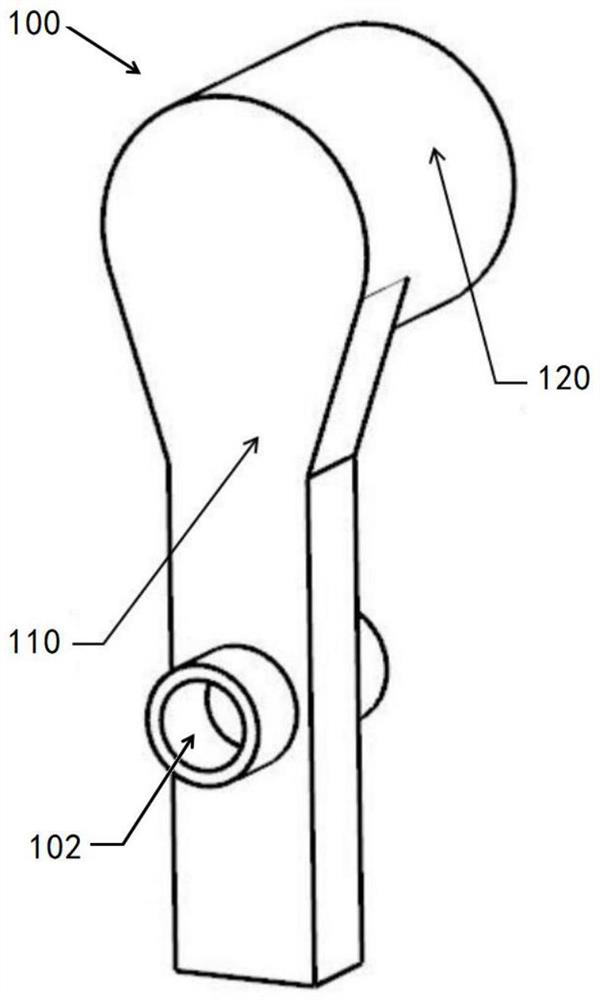
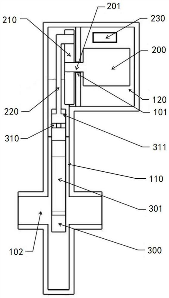
[0037] like figure 1 and figure 2 As shown, a water and fertilizer flow regulating valve includes a valve body 100. The valve body 100 is provided with a water passage chamber 110 and a water isolation chamber 120. The water passage chamber 110 and the water isolation chamber 120 are separated by a partition plate 101. The water passage chamber 110 The connecting nozzle 102 is connected to the water supply pipeline, and there will be a small amount of water inside, and the water-proof cavity 120 is waterproof to prevent water from entering the interior.

[0038] The water passage chamber 110 extends vertically, and includes oppositely arranged distal and proximal ends, that is, as figure 2 As shown, the distal end of the water passage chamber 110 is located above, and the proximal end of the water passage chamber 110 is located below.

[0039] A water blocking cavity 120 is disposed on the side of the distal end of the water passing cavity 110 , and a driving member 200 is...

Embodiment 2

[0050] A kind of regulation method based on the water and fertilizer flow regulating valve in embodiment 1, comprising:

[0051] Start cycle mode or timed mode depending on the difference in water flow required.

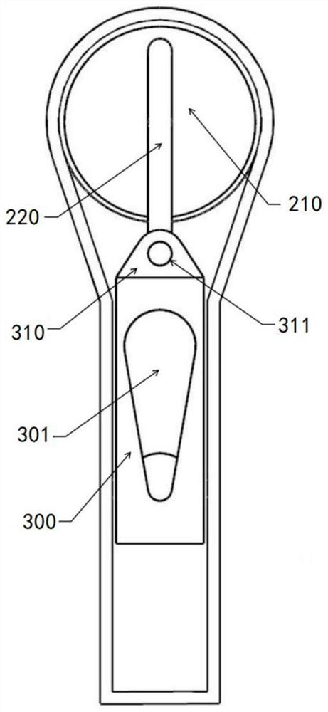
[0052] Specifically, in the cycle mode, the driving member 200 is controlled to work continuously for a preset time. That is, in the circulation mode, the driving member 200 starts to drive the transmission disc 210 to rotate, and the L-shaped transmission rod 220 brings the adjustment piece 300 to move upward. The flow rate is also the smallest, and then the drive disc 210 with the adjustment piece 300 moves downward, the water passing area gradually increases, and the flow rate gradually increases. When the adjustment piece 300 moves to the bottom (lowest position), the adjustment hole 301 returns to the original state, the water passing area is the largest, and then it enters the next startup cycle.

[0053] In the timing mode, the driving member 200 is controll...


PUM


Abstract

The invention discloses a water and fertilizer flow regulating valve and a regulating method, and belongs to the technical field of valves. In order to solve the problem that washing is inconvenient in water and fertilizer integration, the water and fertilizer flow regulating valve comprises a valve body, a water passing cavity and a water separation cavity are formed in the valve body, the water passing cavity vertically extends and comprises a far end and a near end which are oppositely arranged, the water separation cavity is formed in the side edge of the far end, and connecting pipe openings are formed in the two sides of the near end correspondingly; a driving part is arranged in the water separation cavity, the driving part is connected with a controller, the driving end of the driving part extends into the water passing cavity and is connected with a transmission disc, the transmission disc is rotationally connected with one end of an L-shaped transmission rod, and the other end of the L-shaped transmission rod faces the near end and is rotationally connected with an adjusting piece; the size of the adjusting piece is matched with the size of the water passing cavity, an adjusting hole is formed in the adjusting piece in the thickness direction of the adjusting piece, the water flow is adjusted, and then pulse flushing is achieved.

Description

technical field [0001] The invention relates to the technical field of valves, in particular to a water and fertilizer flow regulating valve and a regulating method. Background technique [0002] The integration of water and fertilizer is an emerging agricultural technology that combines fertilization and irrigation, which can greatly improve the efficiency of fertilizer and water use. However, in practical applications, it is easy to cause blockage of filters and drip irrigation belt drippers, which will eventually lead to irrigation systems. error occured. At this time, flushing is generally carried out to restore smooth flow, and because pulse flushing can greatly improve flushing efficiency and enhance flushing effect, it is expected to be widely used, but to generate pulsed water flow requires the use of variable frequency pumps, which are expensive, making the irrigation system Retrofit costs are high. Therefore, there are also modifications to the valve to generate ...

Claims


Application Information

Patent Timeline
Patent Type & Authority Applications(China)
IPC IPC(8): F16K3/02F16K31/04F16K31/44A01C23/00
CPCF16K3/02F16K3/0254F16K31/04F16K31/44A01C23/007Y02P60/21
Inventor 吴七斤刘圆圆张鸣席志尹飞仇勇李勋章姓海涛高中光宋建村池丽敏张朝利
Owner NANJING CUIZHI WATER CONSERVANCY TECH CO LTD
Why Eureka
Try Eureka