Servo test system

A testing system and viscous coefficient technology, applied in the servo field, can solve the problems of the loading test method without the system equivalent inertia, the inability to ensure the availability of the tested servo equipment, and the inability to accurately test the performance of the servo variable speed section and the dynamic adjustment performance of the servo.

Pending Publication Date: 2022-07-12
GUANGDONG KOSSI INTELLIGENT TECH CO LTD
View PDF9 Cites 0 Cited by
  • Summary
  • Abstract
  • Description
  • Claims
  • Application Information

AI Technical Summary

Problems solved by technology

[0004] First, this type of loading test method only considers the load operation under fixed inertia, and cannot accurately test the performance of the servo variable speed section and the dynamic adjustment performance of the servo, nor can it accurately simulate the application conditions of variable inertia and variable load. Test Scenario Limitations
[0005] Second, this type of loading test method does not have an accurate equivalent inertia of the system, which means that this type of test method ignores the influence of factors such as inertia on the actual working conditions, resulting in a large difference between the test results and the actual application results, and cannot ensure that the tested The usability of servo equipment in specific scenarios cannot obtain accurate test results under various working conditions
[0006] In short, the existing test systems and methods cannot well meet the test requirements of variable inertia and variable load, etc.
Based on this, this application proposes a servo test system, which can overcome the above-mentioned problems that cannot meet the test requirements of variable inertia and variable load.

Method used


Image

  • Servo test system
  • Servo test system
  • Servo test system

Examples


Embodiment Construction

[0043] The technical solutions in the embodiments of the present application will be clearly and completely described below with reference to the drawings in the embodiments of the present application. Obviously, the described embodiments are only a part of the embodiments of the present application, but not all of the embodiments. Based on the embodiments in this application, all other embodiments obtained by those of ordinary skill in the art without creative efforts shall fall within the protection scope of this application.

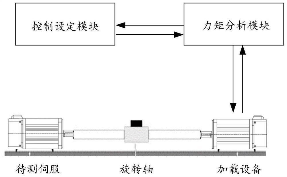
[0044] Next, the application scheme is introduced, see figure 1 , figure 1This is a schematic diagram of a servo testing system disclosed in an embodiment of the present application.

[0045] like figure 1 As shown, the system may include: a control setting module, a torque analysis module and a loading device, wherein the loading device is connected with the servo to be tested through a rotating shaft. Combine below figure 1 , the modules and dev...


PUM


Abstract

A servo test system comprises a control setting module, a torque analysis module and a loading device, and the loading device is connected with a servo to be tested through a rotating shaft. The control setting module is used for determining an inertia value and a load torque value for testing the to-be-tested servo, and sending the inertia value and the load torque value of the to-be-tested servo to the torque analysis module; the torque analysis module is used for acquiring an acceleration value of a rotating shaft of the servo to be tested in real time, determining a control torque value according to the received inertia value, the load torque value and the acquired acceleration value, and sending the control torque to the loading equipment; and the loading equipment is used for receiving the control torque value and loading the control torque corresponding to the control torque value to the servo to be tested connected with the rotating shaft of the loading equipment. According to the invention, the inertia value and the load torque value for testing the to-be-tested servo are converted into the corresponding control torque to realize the simulation test, so that the test requirements of variable inertia and variable load in the servo test process can be realized.

Description

technical field [0001] The present application relates to the field of servo technology, and more particularly, to a servo test system. Background technique [0002] With the development of economy and society, the wide application of servo equipment such as robots has become an inevitable trend of development. In this process, the testing of the servo equipment is particularly important. In order to enable the servo equipment to adapt to the realization of functions in a variety of complex scenarios, it is often necessary to provide different test environments to simulate the operation of the servo equipment under different conditions. Among them, the load occasion with variable inertia is one of the common occasions of the servo system. How to verify the performance of the servo under this type of load condition is very important and necessary. [0003] At present, the servo system often uses a dynamometer or a motor to simulate the test of the towed platform. These two m...

Claims


Application Information

Patent Timeline
Patent Type & Authority Applications(China)
IPC IPC(8): G01L3/00G01M1/10G01M99/00
CPCG01L3/00G01M1/10G01M99/007
Inventor 吴浩陈标发张金泽张强乔志超马茜茜
Owner GUANGDONG KOSSI INTELLIGENT TECH CO LTD
Why Eureka
Try Eureka