
Non-cooperative unmanned aerial vehicle track distribution prediction method based on flight state division

A flight state and distribution prediction technology, applied in mechanical equipment, combustion engines, internal combustion piston engines, etc., can solve the problems of narrowing the trajectory space range, low prediction accuracy of future trajectory points, and difficult to predict intentions, and achieve accurate trajectory distribution. The effect of predicting and narrowing the scope of the trajectory space

Pending Publication Date: 2022-07-12
NANJING UNIV OF AERONAUTICS & ASTRONAUTICS
View PDF0 Cites 2 Cited by
  • Summary
  • Abstract
  • Description
  • Claims
  • Application Information

AI Technical Summary

Problems solved by technology

[0004] Aiming at the deficiencies of the above-mentioned prior art, the object of the present invention is to provide a non-cooperative unmanned aerial vehicle trajectory distribution prediction method based on flight state division, to solve the problem that the trajectory prediction method in the prior art is ineffective when facing non-cooperative targets. The intention of the man-machine operator is difficult to predict, and the prediction accuracy of future trajectory points is not high, which leads to the problems of missing or false alarms; the method of the present invention divides the initial flight state of the UAV, and combines the probability distribution prediction to replace the future trajectory point prediction, and generates Trajectory distribution space, reducing the occurrence of missed alarms and false alarms, and at the same time narrowing the range of trajectory space with non-zero probability to achieve more accurate trajectory distribution prediction

Method used


Image

  • Non-cooperative unmanned aerial vehicle track distribution prediction method based on flight state division
  • Non-cooperative unmanned aerial vehicle track distribution prediction method based on flight state division
  • Non-cooperative unmanned aerial vehicle track distribution prediction method based on flight state division

Examples


Embodiment Construction

[0146] In order to facilitate the understanding of those skilled in the art, the present invention will be further described below with reference to the embodiments and the accompanying drawings, and the contents mentioned in the embodiments are not intended to limit the present invention.

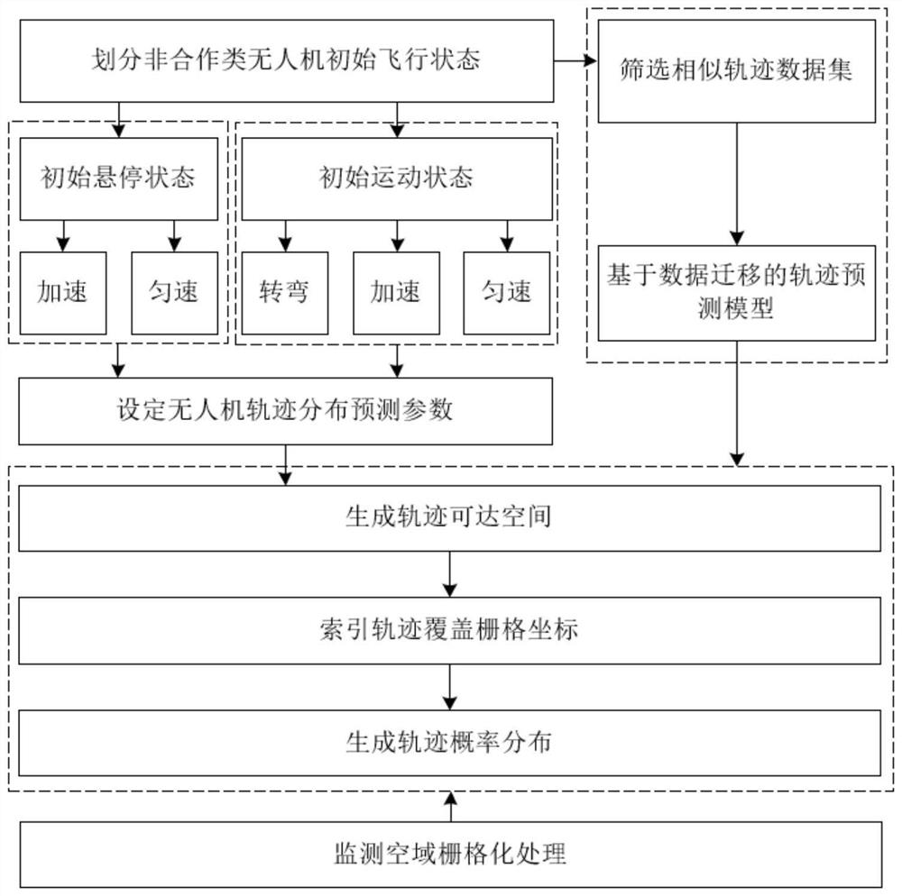
[0147] refer to figure 1 As shown in the present invention, a method for predicting the trajectory distribution of non-cooperative UAVs based on the division of flight states, the steps are as follows:

[0148] (1) According to the scope of the selected monitoring airspace, construct a rasterized airspace;

[0149] Wherein, the monitoring airspace range takes the lower left corner as the origin to establish the airspace Cartesian coordinate system LL, and by setting the number of grids on the x-axis and the y-axis, the airspace is divided into grid sets with unique coordinates, and the grid coordinates are (i,j) indicates that the grid is the i-th grid in the x-axis direction of the airsp...


PUM


Abstract

The invention discloses a non-cooperative unmanned aerial vehicle track distribution prediction method based on flight state division, and the method comprises the following steps: constructing a rasterized airspace for the range of a selected monitoring airspace; dividing the flight state of the unmanned aerial vehicle; screening a similar trajectory data set, and constructing a trajectory prediction model based on data migration; generating a track reachable space; the index track covers the grid coordinates; a trajectory probability distribution is generated. According to the method, the flight state of the unmanned aerial vehicle is subdivided, a trajectory prediction method based on data migration is combined, the motion considering the uncertainty of the intention of an unmanned aerial vehicle operator is modeled as Brownian motion, and the position distribution of the non-cooperative unmanned aerial vehicle is modeled by adopting a truncated Brownian bridge method, so that more accurate trajectory distribution prediction is realized; and a non-zero probability track space range is reduced.

Description

technical field [0001] The invention belongs to the technical field of unmanned aerial vehicle traffic management, and in particular relates to a non-cooperative unmanned aerial vehicle trajectory distribution prediction method based on flight state division. Background technique [0002] With the rapid popularization of drones in various industries, the rapid development of low-altitude drones and the increasing demand for flying, air traffic activities are becoming more and more frequent. The research on UAV trajectory prediction technology can promote the safe, orderly and efficient operation of UAVs in limited low-altitude airspace. Calculating the trajectory distribution of UAVs at a certain moment in the airspace is the basis for building a dangerous behavior recognition model. . [0003] Most of the existing trajectory prediction methods obtain the estimated point of the future position of the UAV, not the position interval where the UAV is located. The error exists...

Claims


Application Information

Patent Timeline
Patent Type & Authority Applications(China)
IPC IPC(8): G05D1/10
CPCG05D1/101Y02T10/40
Inventor 羊钊李娜唐荣朱仁伟曾维理包杰丛玮
Owner NANJING UNIV OF AERONAUTICS & ASTRONAUTICS
Learn More