
Compensation circuit, control chip and display device

A technology of compensation circuit and control electrode, which is applied in the field of compensation circuit, control chip and display device, and can solve the problem of low luminous rate of OLED panel

Active Publication Date: 2022-07-12
HKC CORP LTD
View PDF10 Cites 4 Cited by
  • Summary
  • Abstract
  • Description
  • Claims
  • Application Information

AI Technical Summary

Problems solved by technology

[0003] In order to solve the above problems, the present application provides a compensation circuit, a control chip and a display device, which can solve the problem of low luminous efficiency of the OLED panel caused by the threshold voltage drift of the OLED panel

Method used


Image

  • Compensation circuit, control chip and display device
  • Compensation circuit, control chip and display device
  • Compensation circuit, control chip and display device

Examples


Embodiment 2

[0062] The second embodiment of the present application further provides a control chip. The control chip is connected to a scan line of a display panel for inputting a scan signal to the scan line. The control chip includes the compensation circuit provided in the first embodiment.

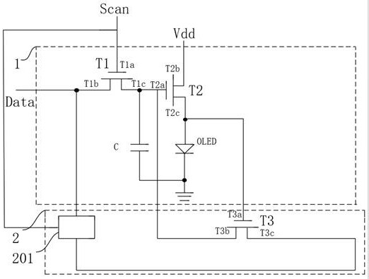
[0063] The control chip can design a compensation circuit 2. The first electrode T3b of the third thin film transistor T3 in the compensation circuit 2 is respectively connected to the control electrode T2a of the second thin film transistor T2 in the driving circuit corresponding to each OLED in the display panel. , so as to perform threshold voltage compensation on the display panel as a whole.

[0064] Optionally, the control chip may design a plurality of compensation circuits 2, each of which corresponds to a display area in the display panel. For example, as Figure 8 As shown, the display panel is divided into 9 areas, then the control chip can design 9 compensation circuits 2, and the fi...

Embodiment 3

[0068] Based on the control chip, the third embodiment of the present application further provides a display device, and the display device includes the control chip provided in the second embodiment.


PUM


Abstract

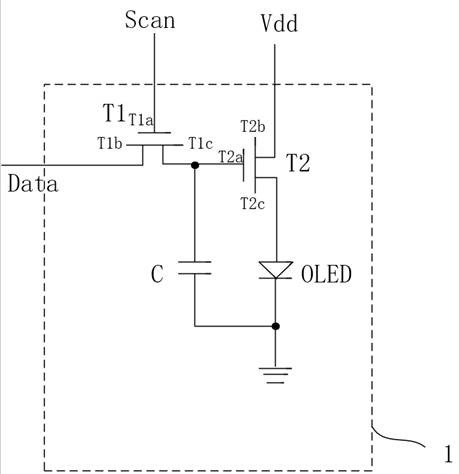
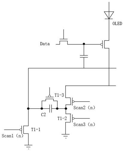
The invention provides a compensation circuit, a control chip and a display device, mainly relates to the technical field of display, and can solve the problem of low luminous efficiency of an OLED panel caused by threshold voltage drift of the OLED panel. The compensation circuit is applied to the driving circuit, and the driving circuit comprises a first thin film transistor, a second thin film transistor, an organic light emitting diode and a capacitor. The compensation circuit comprises a third thin film transistor and a detection module. The control electrode of the third thin film transistor is used for being connected with the second electrode of the second thin film transistor, the first electrode of the third thin film transistor is used for being connected with the control electrode of the second thin film transistor, and the detection module is connected with the second electrode of the third thin film transistor, the scanning line and the data line. And the detection module is used for performing turn-off and turn-on respectively when receiving two adjacent voltage signals output by the second electrode of the third thin film transistor.

Description

technical field [0001] The present invention relates to the field of display technology, in particular to a compensation circuit, a control chip and a display device. Background technique [0002] As a new generation of display devices, organic electroluminescence display (Organic Light-Emitting Diode, OLED) is widely respected for its advantages of self-luminescence and fast response. At present, ThinFilm Transistor (TFT) is commonly used in OLED as an important electronic device. However, in the process of use, TFT has a problem, that is, the threshold voltage of TFT will drift under long-term gate bias, and the luminous brightness of OLED It is determined by the voltage of the TFT. Therefore, the drift of the threshold voltage of the TFT will reduce the luminous brightness of the OLED, thereby affecting the service life of the OLED. SUMMARY OF THE INVENTION [0003] In order to solve the above problems, the present application provides a compensation circuit, a control...

Claims


Application Information

Patent Timeline
Patent Type & Authority Applications(China)
IPC IPC(8): G09G3/3208
CPCG09G3/3208Y02B20/30G09G3/3233G09G2300/0819G09G2300/0842G09G2320/0295G09G2300/0852G09G2310/0262G09G2310/0251H01L29/7869G09G2300/0426G09G2300/0833G09G3/3225G09G2310/0202G09G2320/045
Inventor 周仁杰袁海江
Owner HKC CORP LTD
Learn More