Double-break isolating switch and GIS equipment

An isolating switch and double-break technology, which is applied in the setting of switchgear, switchgear, air switch parts, etc. The effect of clever construction, long life and improved durability

Pending Publication Date: 2022-07-12
PINGGAO GRP +3
View PDF1 Cites 0 Cited by
  • Summary
  • Abstract
  • Description
  • Claims
  • Application Information

AI Technical Summary

Problems solved by technology

[0006] The purpose of the present invention is to provide a double-break isolating switch to solve the problems of easy ablation and short service life of the moving contact seat in the prior art
In addition, a GIS device is also provided to solve the problems of easy ablation and short service life of the movable contact of the disconnector in the GIS device in the prior art

Method used


Image

  • Double-break isolating switch and GIS equipment
  • Double-break isolating switch and GIS equipment
  • Double-break isolating switch and GIS equipment

Examples


specific Embodiment 1

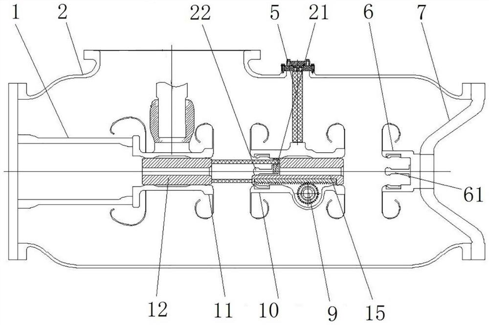
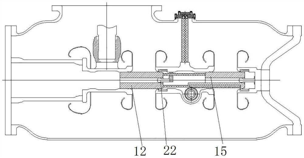
[0062] The GIS equipment of the present invention includes a bus bar, a circuit breaker, a grounding switch and a double-break disconnecting switch.

[0063] like figure 1 and 2 As shown, the double-break disconnect switch includes a housing 2, an insulating support cylinder 1 is fixed on one side of the inner cavity of the housing 2, and a first movable contact seat 11 is fixed on the insulating support cylinder 1. An insulating pot 7 is fixed on the other side, a static contact seat 6 is fixed on the insulating pot 7 , and an arc striking contact 61 of the static contact seat is fixed on the bottom wall of the inner hole of the static contact seat 6 . An insulating support 5 is fixed on the inner wall of the housing in the middle of the inner cavity of the housing 2 , and a second movable contact seat 10 , a first movable contact seat 11 , a second movable contact seat 10 and a static contact seat are fixed on the insulating support 5 6 are arranged at intervals and form t...

Embodiment 1

[0072] The connection block in the first embodiment is integrally arranged with the second movable contact seat. In this embodiment, the connection block is welded on the hole wall of the second movable contact mounting through hole.

specific Embodiment 3

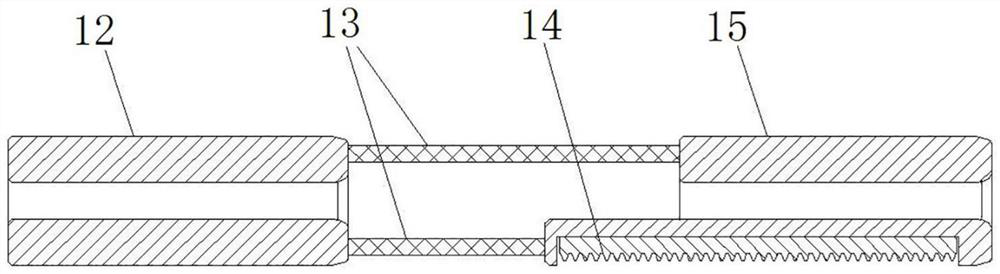
[0074] The insulating connectors in Embodiment 1 are four insulating rods spaced along the circumference of the end face of the first movable contact. In this embodiment, the insulating connectors are insulating cylinders connecting two movable contacts. The end of the 1 is provided with a connecting block with the same structure as the connecting block in Embodiment 1, so as to connect the two moving contacts. In order to avoid the arc-striking contact, the insulating cylinder is provided with an escape groove. The avoidance groove is mainly to avoid the connection block of the arc-striking contact, and the inner cavity of the insulating cylinder is mainly to avoid the contact body of the arc-striking contact.

[0075] In addition, for the case where the second movable contact is provided with an avoidance notch, the insulating cylinder is formed with a circular arc tube segment complementary to the avoidance notch on the second movable contact by cutting, and the avoidance gr...


PUM


Abstract

The invention belongs to the technical field of disconnecting switches, and particularly relates to a fracture structure of a disconnecting switch. The invention provides a double-fracture isolating switch and GIS equipment, and aims to solve the problems that a movable contact seat is easy to ablate and short in service life in the prior art. A first moving contact and a second moving contact of the double-break disconnecting switch are connected through an insulating connecting piece, a second moving contact seat arc striking contact is fixed on a second moving contact seat, and a contact body of the second moving contact seat arc striking contact is fixed on a hole wall of a second moving contact mounting through hole through a connecting block. The second moving contact seat arc striking contact is located in the second moving contact installation through hole, and the position where the insulation connecting piece is located is provided with an avoiding space used for avoiding the second moving contact seat arc striking contact. The arc is mainly generated between the first moving contact and the arc striking contact of the second moving contact seat, and the second moving contact seat is not easy to ablate, so that the second moving contact seat is not easy to damage, and the service life is long.

Description

technical field [0001] The invention belongs to the technical field of isolation switches, and particularly relates to a fracture structure of an isolation switch. Background technique [0002] With the development of economy and society and the improvement of people's living standards, the whole society has higher and higher requirements for the reliability of power supply. Government departments, power regulatory agencies, and media networks are highly concerned about safety in production, making it more and more difficult to plan power outages. However, in order to reduce the cost of infrastructure and operation and maintenance, larger GIS power stations are generally constructed in stages, and most of the GIS power stations need to be expanded. However, only the expansion interface is reserved for the first-phase equipment of GIS products. In order to ensure safety, the busbar power failure is usually required during expansion; At the same time, when a fault occurs in a ...

Claims


Application Information

Patent Timeline
IPC IPC(8): H01H31/02H02B13/035
CPCH01H31/026H02B13/035
Inventor 段晓辉占小猛柴影辉谭盛武魏建巍杨敏董祥渊谢世超高远贺永明温铭丽徐华靳幸福李斐井琼琼鲁世浩庞建白杨张振苏士伟
Owner PINGGAO GRP
Why Eureka
Try Eureka