
PLL circuit and control method thereof

A control method and circuit technology, applied in the direction of automatic power control, electrical components, etc., can solve the problem of increasing chip size

Pending Publication Date: 2022-07-12
ROHM CO LTD
View PDF1 Cites 1 Cited by
  • Summary
  • Abstract
  • Description
  • Claims
  • Application Information

AI Technical Summary

Problems solved by technology

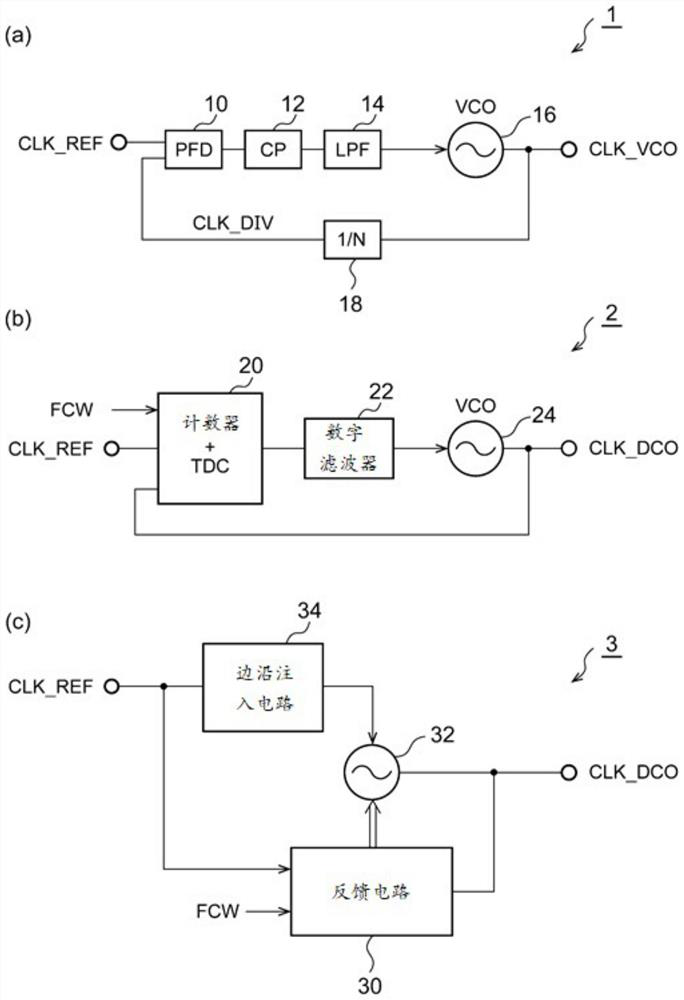
[0004] figure 1 The analog PLL circuit 1 of (a) has been used for a long time in various applications and has high reliability, but there is a problem that the chip size becomes large due to the loop filter

Method used


Image

  • PLL circuit and control method thereof
  • PLL circuit and control method thereof
  • PLL circuit and control method thereof

Examples


Embodiment approach

[0070] Hereinafter, embodiments will be described with reference to the drawings. The same or equivalent components, members, and processes shown in the respective drawings are denoted by the same reference numerals, and overlapping descriptions are appropriately omitted. In addition, the embodiment does not limit the invention, but is merely an illustration, and all the features or combinations described in the embodiment are not the essential content of the invention.

[0071] In this specification, the term "the state in which the member A and the member B are connected" includes not only the case where the member A and the member B are physically directly connected, but also the fact that the member A and the member B do not substantially affect the electrical connection state of the member A and the member B. , or indirectly connected to other components that do not impair the function or effect of their combination.

[0072] Similarly, "the state in which the member C i...


PUM


Abstract

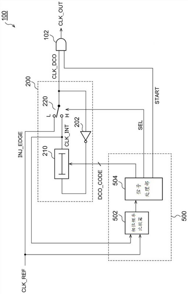
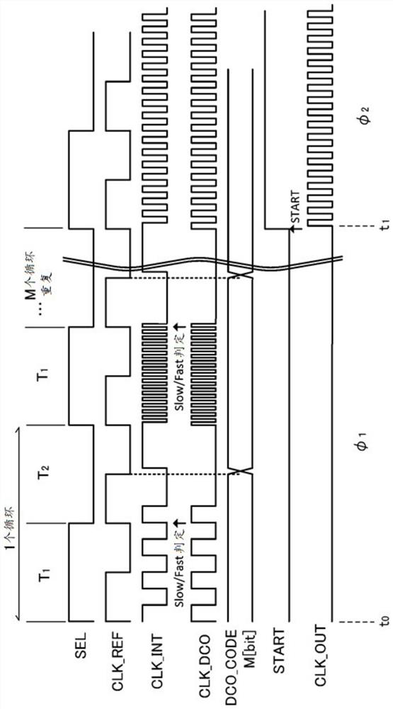
The DCO (200) is configured so as to form a ring oscillator and oscillate at a frequency corresponding to the control code DCO - CODE when the selection signal SEL is in an active period, and so as to be able to inject an injection edge INJ - EDGE based on a reference clock CLK - REF when the selection signal SEL is in an inactive period. During a start-up period of the PLL circuit (100), the controller (500) repeats a cycle including: (i) activating the selection signal SEL, oscillating the DCO (200), and performing a phase comparison between an oscillator clock and a reference clock CLK - REF; and (ii) invalidating the selection signal, stopping the DCO (200), and updating the control code by a dichotomy lookup based on the result of the phase comparison.

Description

technical field [0001] The present disclosure relates to a PLL (Phase Locked Loop) circuit. Background technique [0002] For various ICs (Integrated Circuits), a frequency synthesizer is used that generates a clock of an arbitrary frequency from a reference clock. As such a frequency synthesizer, a PLL circuit is widely used. figure 1 (a)~ figure 1 (c) is a block diagram illustrating the basic structure of the PLL circuit. [0003] exist figure 1 In (a) of , the analog PLL circuit 1 is shown. The analog PLL circuit 1 includes a phase comparator (PFD: Phase Frequency Detector) 10 , a charge pump circuit 12 , a low-pass filter 14 , a voltage controlled oscillator (VCO: Voltage Controlled Oscillator) 16 , and a frequency divider 18 . VCO16 with an analog control voltage V CTRL the corresponding frequency to oscillate. The output clock CLK_VCO of the VCO 16 is divided by 1 / N by the frequency divider 18 . The phase comparator 10 detects the phase difference between the ...

Claims


Application Information

Patent Timeline
Patent Type & Authority Applications(China)
IPC IPC(8): H03L7/083H03L7/099H03L7/10H03L7/24
CPCH03L7/083H03L7/24H03L7/0814H03L7/0995H03L7/0991H03L7/081H03L7/0992H03L2207/50
Inventor 辻将信
Owner ROHM CO LTD
Learn More