Spiral electrode
A helical electrode technology, applied in the field of medical devices, can solve the problems of nerve injury, complicated operation, needle-shaped electrode does not have self-holding ability, etc., and achieve the effect of ensuring the safety of use
- Summary
- Abstract
- Description
- Claims
- Application Information
AI Technical Summary
Problems solved by technology
Method used
Image
Examples
Embodiment 1
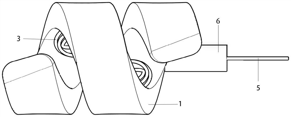
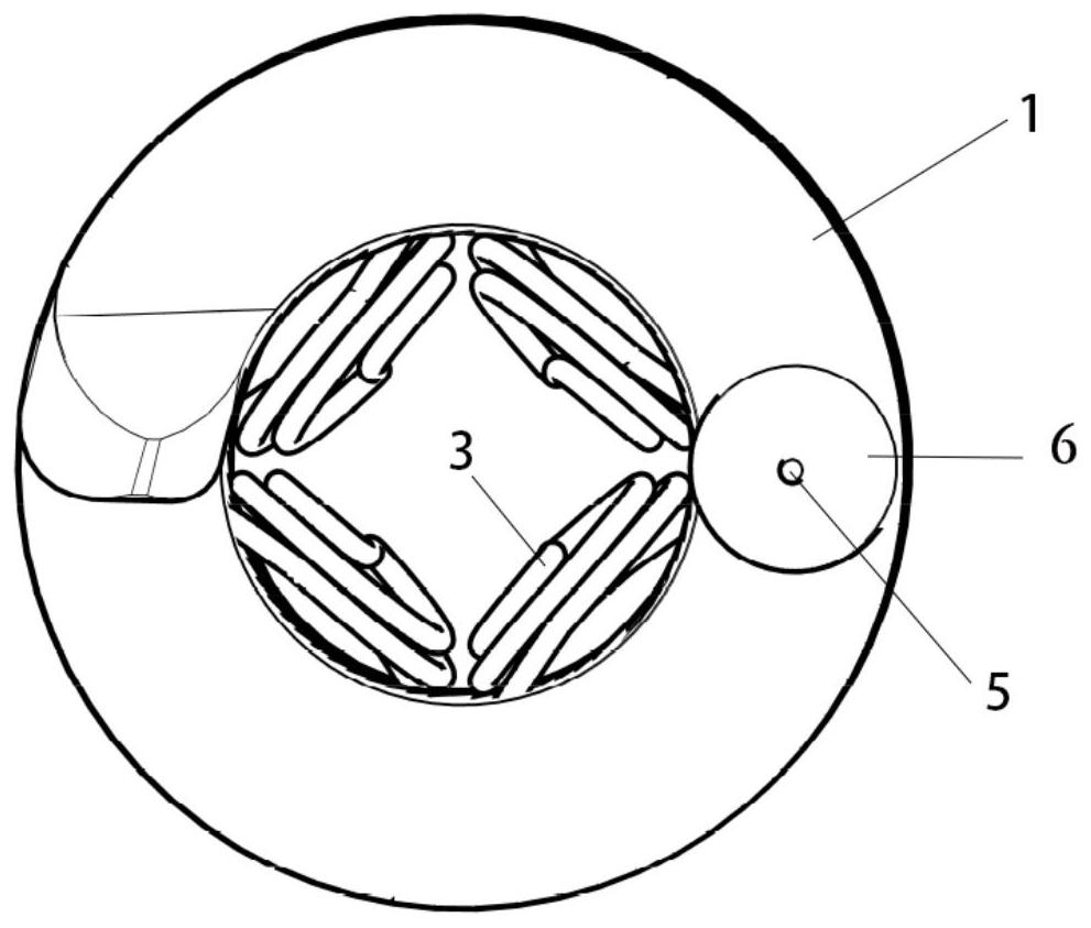
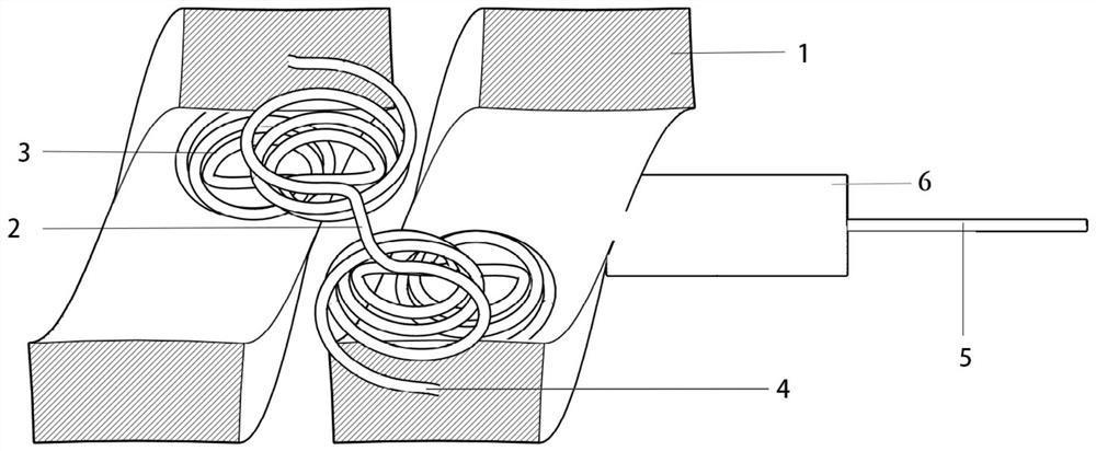
[0030] Example 1, as Figure 1 to Figure 6 As shown, a spiral electrode includes a spiral body 1 and an electrode wire 2. One end of the electrode wire 2 is connected to a wire 5, and the other end extends along the spiral body 1. The contact part 3 of the surface, the contact part 3 is an elastic structure, when in use, the spiral body 1 is wrapped around the nerve or blood vessel to be measured, such as the vestibulocochlear nerve, the contact part of the electrode wire 2 is in contact with the object to be measured, and the spiral body The inner diameter of 1 is set to the maximum diameter of the object to be tested. If the object to be tested is the vestibulocochlear nerve, it is set to the maximum diameter of the vestibulocochlear nerve in healthy people. Spirosome 1 is a biocompatible insulating material, such as medical Silicone rubber, polyurethane.
Embodiment 2
[0031] Example 2, as Figure 1 to Figure 6 As shown, this embodiment is a further improvement carried out on the basis of Embodiment 1, and the details are as follows:
[0032] The contact portion 3 is a helical structure, the axis of the helical structure intersects perpendicularly with the axis of the helical body 1, and the contact portion 3 can elastically deform in the direction perpendicular to the axis of the helical body 1. When the contact portion 3 contacts the object to be tested, it can be compressed. Avoid damage to the object to be measured by the electrode wire 2.
Embodiment 3
[0033] Example 3, as Figure 1 to Figure 6 As shown, this embodiment is a further improvement carried out on the basis of Embodiment 2, and the details are as follows:
[0034] The contact part 3 and the embedded part 4 are arranged at intervals along the extension direction of the spiral body 1, and the contact parts 3 are arranged at least once around the axis of the spiral body 1, so that the whole circle of the object to be tested can be in contact with the contact part 3, and the monitoring is more accurate and effective.
PUM
 Abstract
Description
Claims
Application Information
 - R&D
- Intellectual Property
- Life Sciences
- Materials
- Tech Scout
- Unparalleled Data Quality
- Higher Quality Content
- 60% Fewer Hallucinations
Browse by: Latest US Patents, China's latest patents, Technical Efficacy Thesaurus, Application Domain, Technology Topic, Popular Technical Reports.
© 2025 PatSnap. All rights reserved.Legal|Privacy policy|Modern Slavery Act Transparency Statement|Sitemap|About US| Contact US: help@patsnap.com


