Head fixing device for ultrasonic guided neck minimally invasive interventional operation

A minimally invasive intervention and fixation device technology, applied in the direction of providing sterile surgical environment equipment, stereotaxic surgical equipment, etc., can solve the problem of easy tilting and fixing of the patient's head, achieve head comfort, improve comfort, The effect of refreshing the environment

Pending Publication Date: 2022-07-15
唐正平
View PDF1 Cites 0 Cited by
  • Summary
  • Abstract
  • Description
  • Claims
  • Application Information

AI Technical Summary

Problems solved by technology

[0005] In order to overcome the disadvantages that the above-mentioned prior art cannot accurately fix the patient's head and the patient's head is easy to tilt, the technical problem to be solved by the present invention is to provide a method that can correct the position of the patient's head, accurately The patient's head is fixed to reduce the shaking degree and frequency of the operation process. The head fixation device for ultrasound-guided neck minimally invasive interventional surgery

Method used


Image

  • Head fixing device for ultrasonic guided neck minimally invasive interventional operation
  • Head fixing device for ultrasonic guided neck minimally invasive interventional operation
  • Head fixing device for ultrasonic guided neck minimally invasive interventional operation

Examples


Embodiment 1

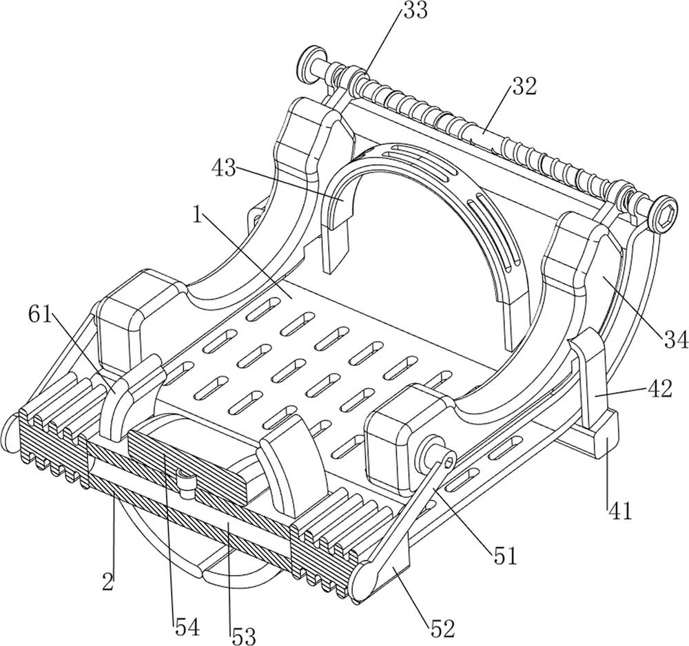
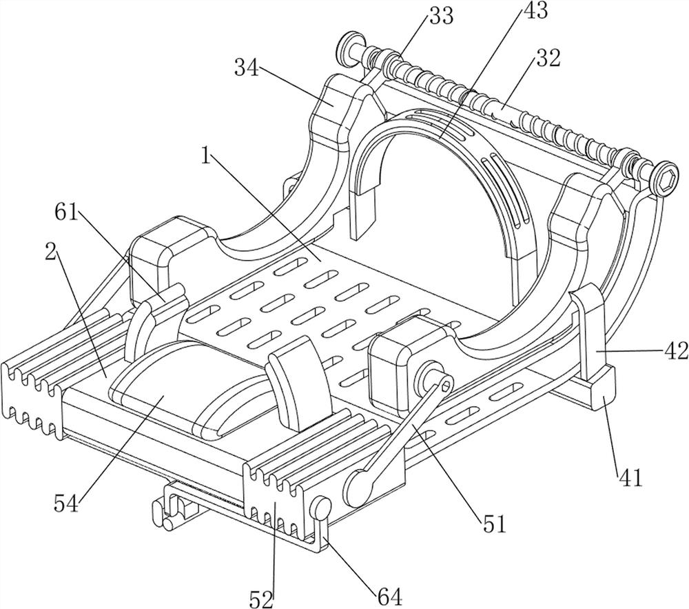
[0032] A head immobilization device for ultrasound-guided minimally invasive cervical interventional surgery, such as figure 1 and Figure 4 As shown, it includes a cushion 1, a mounting block 2, a buffer mechanism 3 and a restraint mechanism 4. The left side of the cushion 1 is bolted with a mounting block 2, and the cushion 1 is provided with a cushion mechanism 3, and between the cushion mechanism 3 and the cushion 1 Binding mechanism 4.

[0033] like Figure 4 As shown, the buffer mechanism 3 includes a support block 31, a two-way screw 32, a nut 33 and a buffer block 34. The upper side of the back cushion 1 is slidably provided with two buffer blocks 34, and the two buffer blocks 34 are arranged symmetrically in the front and rear. A support block 31 is bolted symmetrically on the upper side of the right part of the 1 in front and rear, and a bidirectional screw rod 32 is rotatably penetrated between the upper parts of the two support blocks 31. The bidirectional screw ...

Embodiment 2

[0037] On the basis of Example 1, as figure 1 , figure 2 and image 3 As shown, it also includes a heightening mechanism 5, the heightening mechanism 5 includes a squeeze plate 51, an air bag 52 and a heightening air cushion 54, the interior of the mounting block 2 is provided with an air supply hole 53, and the middle upper side of the mounting block 2 is connected with a heightening air cushion 54. Airbags 52 are symmetrically connected to the front and rear sides of the installation block 2. The two airbags 52 and the heightening air cushion 54 are connected through the air supply hole 53. The left side of the two buffer blocks 34 is symmetrically connected to the bolt. A squeeze plate 51 is connected.

[0038] By increasing the air cushion 54, the neck of the patient can be supported, so that the neck of the patient is more comfortable. When the buffer blocks 34 on the front and rear sides move in opposite directions, the buffer blocks 34 on the front and rear sides res...

Embodiment 3

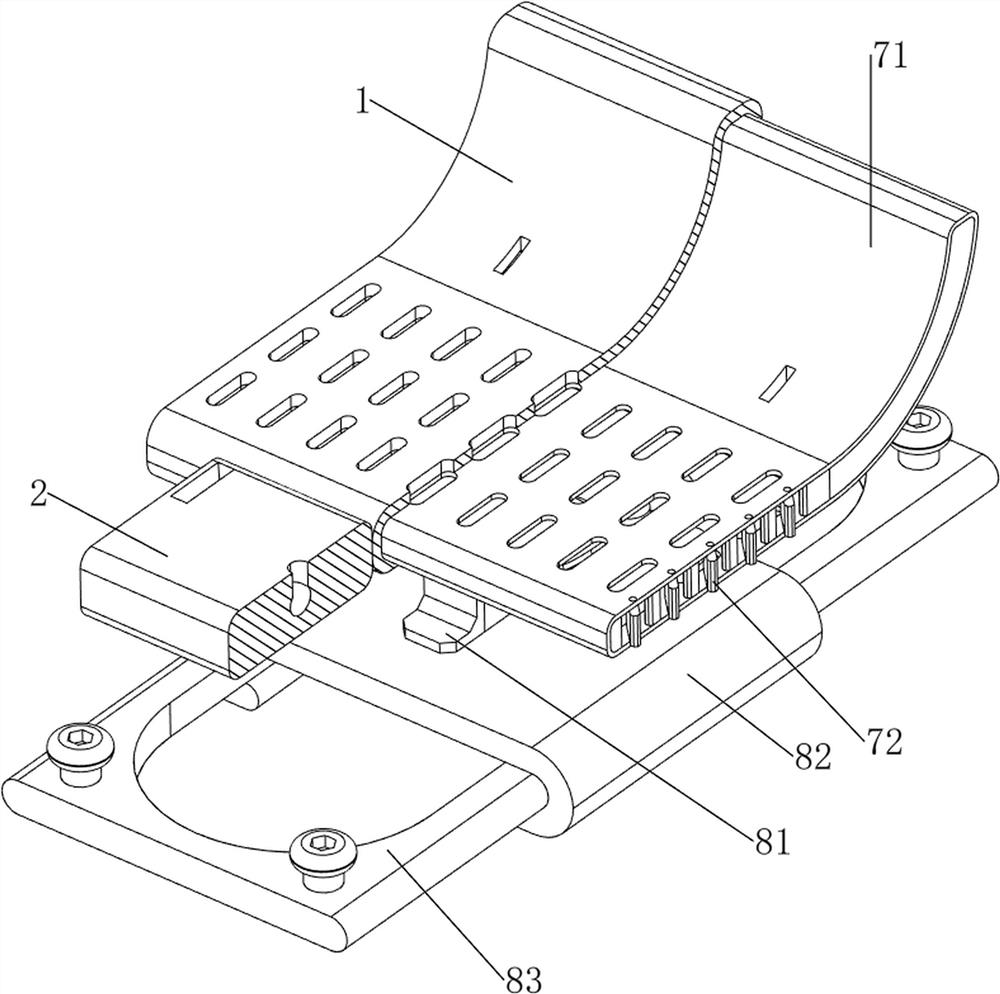
[0040] On the basis of Example 2, as figure 1 , Figure 5 and Image 6 As shown, it also includes a protection mechanism 6, the protection mechanism 6 includes a second sponge pad 61, a squeeze rod 62, a return spring 63 and a push plate 64, and the right part of the installation block 2 slides through two second sponge pads 61. The two second sponge pads 61 are arranged symmetrically in the front and rear. A squeeze rod 62 is bolted on the left side of the lower part of the second sponge pad 61. A return spring 63 is connected between the squeeze rod 62 and the mounting block 2. Two airbags A push plate 64 is symmetrically bolted on one side of the left part of 52 away from each other.

[0041] When the pressing plate 51 squeezes the airbag 52 and the airbag 52 is compressed, the airbags 52 on the front and rear sides respectively drive the push plates 64 on the front and rear sides to move in the opposite direction, and the push plates 64 on the front and rear sides respec...


PUM


Abstract

The invention relates to a fixing device, in particular to a head fixing device for an ultrasonic guided neck minimally invasive interventional operation. The head fixing device for the ultrasonic guided neck minimally invasive interventional operation can correct the position of the head of a patient, accurately fix the head of the patient and reduce the shaking degree and frequency in the operation process. The head fixing device comprises a back cushion, a mounting block, a buffering mechanism, a binding mechanism and the like, the left side of the back cushion is connected with the mounting block, the buffering mechanism used for buffering and damping is arranged on the back cushion, and the binding mechanism is arranged on the back cushion. And a binding mechanism for stabilizing the head of the patient is arranged between the buffer mechanism and the back cushion. The ears of a patient are clamped through the buffer blocks on the front side and the rear side, so that the position of the head of the patient can be corrected, the head of the patient is accurately fixed, and the shaking degree and frequency in the operation process are reduced.

Description

technical field [0001] The invention relates to a fixation device, in particular to a head fixation device for ultrasound-guided minimally invasive cervical interventional surgery. Background technique [0002] With the continuous development and progress of medical science and technology, the concept of "minimally invasive" has penetrated into various fields of surgery. Since minimally invasive surgery is an operation with less trauma, less pain and faster recovery, this type of operation It is widely used in the medical field. When performing minimally invasive neck surgery, the stability of the patient's head is an important factor affecting the minimally invasive surgery. A slight shaking can easily lead to the normal operation of the operation. In order to avoid the patient's head shaking, the patient needs to be moved in advance head fixed. The existing methods all use special fixation devices to fix the patient's head. [0003] For example, the patent authorization...

Claims


Application Information

Patent Timeline
Patent Type & Authority Applications(China)
IPC IPC(8): A61B90/14A61B90/40
CPCA61B90/14A61B90/40A61B2090/401
Inventor 唐正平
Owner 唐正平
Why Eureka
Try Eureka