Overwrist joint splint and using method thereof

A technology of wrist joint and splint, which is applied in the field of supra-wrist joint splint, can solve the problems that the gypsum supra-wrist joint cannot achieve the stability of the splint, cannot achieve the stability of the splint, and cannot be well grasped by the patient, so as to benefit the healing of the bone and benefit the The effect of smooth blood transportation and ensuring reliability

Pending Publication Date: 2022-07-15
贵州澳特拉斯科技有限公司
View PDF0 Cites 0 Cited by
  • Summary
  • Abstract
  • Description
  • Claims
  • Application Information

AI Technical Summary

Problems solved by technology

[0002] At present, two forms of plaster or splint are used for medical fixation. The plaster superimposes the wrist joint, while the splint does not supersede the wrist joint. Both have their own advantages at different times of fracture. Usually, a plaster cast is used, which cannot achieve the all-round stability of the splint, and the super-wrist fixation in the later stage of fracture restricts the exercise of limb function; the traditional splint is four pieces, and the fixation of the fracture end is more three-dimensional, and the non-super-articular fixation in the later stage of fracture can be protected by the splint Functional exercise is better than plaster cast, but super-joint fixation is more stable in the early stage of fracture, and the adjustment of splint fixation straps needs to be done many times and is highly professional, which i

Method used

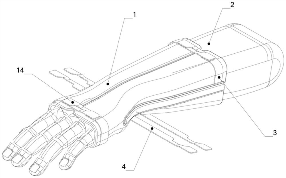
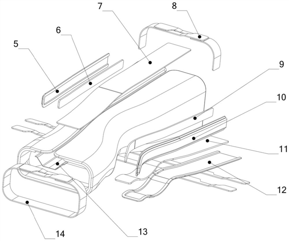
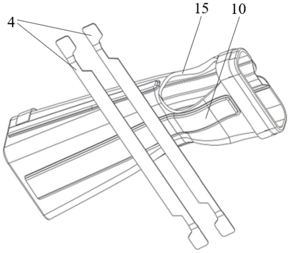

Image

  • Overwrist joint splint and using method thereof
  • Overwrist joint splint and using method thereof
  • Overwrist joint splint and using method thereof

Examples


Embodiment Construction

[0023] Various exemplary embodiments, features and aspects of the present application will be described in detail below with reference to the accompanying drawings. The same reference numbers in the figures denote elements that have the same or similar functions. While various aspects of the embodiments are shown in the drawings, the drawings are not necessarily drawn to scale unless otherwise indicated.

[0024] Among them, it should be understood that the terms "center", "portrait", "horizontal", "length", "width", "top", "bottom", "front", "rear", "left", "right" ", "Vertical", "Horizontal", "Top", "Bottom", "Inner", "Outer", "Clockwise", "Counterclockwise", "Axial", "Radial", "Circumferential" The orientation or positional relationship indicated by "" etc. is based on the orientation or positional relationship shown in the accompanying drawings, which is only for the convenience of describing the present application or simplifying the description, rather than indicating o...


PUM

PropertyMeasurementUnit
Angleaaaaaaaaaa
Bending angleaaaaaaaaaa

Abstract

The invention relates to an over-wrist joint splint which comprises an arm sleeve, a framework plate and a framework sleeve pocket. The circumferential size of the arm sleeve at the wrist joint is smaller than the sizes of the two ends of the arm sleeve; the framework sleeve pockets are arranged on the outer side of the arm sleeve in the axial direction, the opening direction of the framework sleeve pockets is the same as that of the end opening of the arm sleeve, and the multiple framework sleeve pockets are arranged in the circumferential direction of the arm sleeve at intervals; the framework plate is in a long strip shape and can be installed in the matched framework sleeve pocket in a penetrating mode. And framework plates with different lengths and different widths can be adapted to the interior of the framework sleeve pocket. The skeleton plate of the over-wrist joint is arranged in the skeleton sleeve pocket in the early stage of fracture to ensure that the wrist joint is absolutely fixed in the early stage of fracture, and the skeleton plate of the over-wrist joint is taken out of the skeleton sleeve pocket and replaced with a short non-over-wrist joint skeleton plate in the middle and later stages of fracture, so that the motion range of the wrist is increased on the basis of retaining the forearm fixing function, and the fracture fixation effect is improved. Therefore, the patient can consciously increase the motion range of the wrist, and the purpose of early functional exercise is achieved.

Description

technical field [0001] The present application relates to the field of medical devices, in particular to a super wrist splint and a method for using the same. Background technique [0002] At present, two forms of plaster or splint are used for medical fixation. The plaster is over the wrist joint and the splint is not over the wrist joint. Both have their own advantages at different times of the fracture. The plaster over the wrist controls the rotation and prevents rotational displacement after the fracture, but the plaster fixation Usually plaster support is used, which cannot achieve the all-round stability of the splint, and the over-wrist fixation in the later stage of the fracture limits the functional exercise of the limbs; the traditional splint is four pieces, and the fixation of the fracture end is more three-dimensional, and the non-over-joint fixation in the later stage of the fracture can be protected by the splint Functional exercise is better than plaster sup...

Claims


Application Information

Patent Timeline
IPC IPC(8): A61F5/058
CPCA61F5/05866
Inventor 朱红文李海波刘贵臻刘进新
Owner 贵州澳特拉斯科技有限公司
Why Eureka
Try Eureka