Eureka AIR delivers breakthrough ideas for toughest innovation challenges, trusted by R&D personnel around the world.

Automatic demolding method applied to automobile plastic part and injection mold thereof

An injection mold and automatic demoulding technology, applied in the direction of coating, etc., can solve the problems of reducing mold temperature, increasing device energy consumption, and unavoidable injection molded parts not being affected by exhaust gas, so as to eliminate product failure and improve work efficiency Effect

Pending Publication Date: 2022-07-15
CHANGSHA SHENDA TECH GRP CORP
View PDF0 Cites 0 Cited by
  • Summary
  • Abstract
  • Description
  • Claims
  • Application Information

AI Technical Summary

Problems solved by technology

[0002] Injection mold is a tool for producing plastic products, and it is also a tool for giving plastic products a complete structure and precise dimensions. At present, in the existing injection molding method, the plastic melted by heat is injected into the mold cavity by high pressure from the injection molding machine, and it is cooled and solidified. Finally, molded products are obtained; in the process of producing injection molded parts, the temperature of the mold needs to be repeatedly raised and lowered to ensure that the injection molding material can be filled to any position in the mold cavity, which increases the energy consumption of the device during the production process. At the same time, for complex injection molded parts, the qualified rate of injection molded parts cannot be guaranteed, and the injection molded parts cannot be prevented from being affected by exhaust.

Method used


Image

  • Automatic demolding method applied to automobile plastic part and injection mold thereof
  • Automatic demolding method applied to automobile plastic part and injection mold thereof
  • Automatic demolding method applied to automobile plastic part and injection mold thereof

Examples


Embodiment Construction

[0041] The present invention will be further described below with reference to the accompanying drawings and specific embodiments.

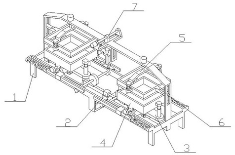
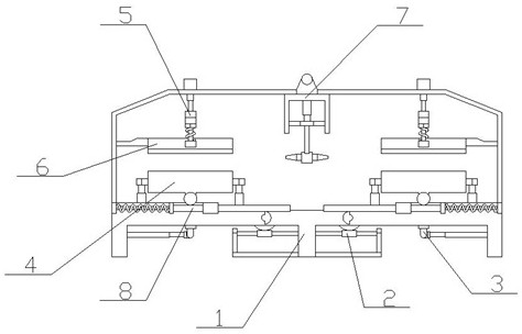
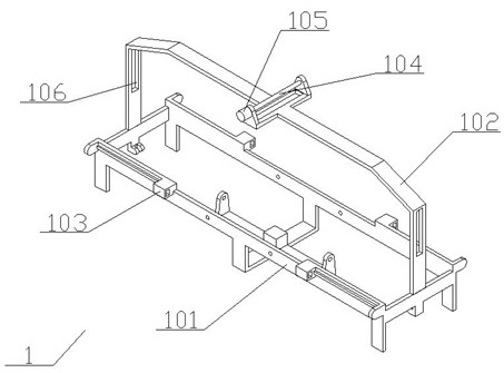
[0042] Combine below Figure 1-7 Describe the specific embodiment of the present invention, an automatic demolding method applied to automobile plastic parts and an injection mold thereof,

[0043] An automatic demolding method applied to automobile plastic parts is characterized in that: comprising the following steps:

[0044] Step 1: Make the injection molding material thicker, use the spraying device to spray the injection molding material on the sub-mold of the mold and then remove the spraying device;

[0045] Step 2: Combine the child and master molds of the mold, and separate the child and master molds after the injection molding material is completely cooled by compression molding;

[0046] Step 3: Press the edge of the mold to remove the burrs of the plastic parts during the demoulding process.

[0047] An injection mold applied to a...


PUM


Abstract

The invention provides an automatic demolding method applied to an automobile plastic part and an injection mold of the automobile plastic part. The method comprises the following steps that an injection molding material is prepared to be thick, a spraying device is used for spraying the injection molding material to a child mold and a mother mold of the mold, and then the spraying device is removed; combining the son mold and the mother mold of the mold, and separating the son mold and the mother mold after the injection molding material is completely cooled through compression molding; the edge of the mold is pressed to remove burrs of the plastic part in the demolding process; the injection mold comprises two turnover mechanisms which are arranged on the two sides of the supporting mechanism in a bilateral symmetry mode, and each turnover mechanism is provided with a mold mechanism. The power mechanism is arranged in the middle of the supporting mechanism; the spraying mechanism is arranged in the middle of the upper side of the supporting mechanism; compared with a traditional injection molding device, the arrangement that a plastic part is generated in a spraying and compression molding mode does not need to change the temperature of a child mold and a mother mold of the mold in the injection molding process, and the child mold and the mother mold of the mold can be directly closed under the low-temperature constant condition for plastic compression molding.

Description

technical field [0001] The invention relates to the technical field of injection molding of automobile plastic parts, in particular to an automatic demoulding method applied to automobile plastic parts and an injection mold thereof. Background technique [0002] Injection mold is a tool for producing plastic products, and it is also a tool for giving plastic products complete structure and precise size. At present, in the existing injection molding methods, the heated and melted plastic is injected into the mold cavity by high pressure from the injection molding machine, and it is cooled and solidified. Then, a molded product is obtained; in this method, the temperature of the mold needs to be repeatedly raised and lowered during the production of injection molded parts to ensure that the injection material can be filled to any position in the mold cavity, which increases the energy consumption of the device during the production process. At the same time, for complex inject...

Claims


Application Information

Patent Timeline
Patent Type & Authority Applications(China)
IPC IPC(8): B29C37/00B29C37/02B29C45/40B29C45/68B29C45/17
CPCB29C37/0067B29C37/02B29C45/4005B29C45/68B29C45/1756B29C45/1753
Inventor 王民强环晓建陈毕泉
Owner CHANGSHA SHENDA TECH GRP CORP
Why Eureka
Eureka Blog
Learn More