Waterway system for intelligent closestool

A smart toilet and waterway technology, applied to water supply devices, flushing equipment with water tanks, sanitary equipment for toilets, etc., can solve the problems of small adjustable space, high control resources, and multiple structural spaces, so as to reduce the cost of control resources effect of demand

Pending Publication Date: 2022-07-15
HUNAN MEGMEET ELECTRICAL TECH CO LTD
View PDF0 Cites 0 Cited by
  • Summary
  • Abstract
  • Description
  • Claims
  • Application Information

AI Technical Summary

Problems solved by technology

Therefore, the independently set cleaning waterway itself has more logical components, takes up high hardware and software system control resources, and also occupies a lot of structural space inside the product. Not only is the control complicated, but it is also not convenient for the expansion of other functions.
In addition, there is no controllable energy input for the flow and pressure in the cleaning waterway. Constrained by the pipe pressure of the tap water itself, the upper limit of the obtained cleaning water pressure is solidified, and the adjustable space is small, which is not convenient for developing new cleaning effects. Once the tap water supply pressure, When the flow rate is insufficient, the basic cleaning function will also be lost

Method used


Image

  • Waterway system for intelligent closestool
  • Waterway system for intelligent closestool
  • Waterway system for intelligent closestool

Examples


Embodiment

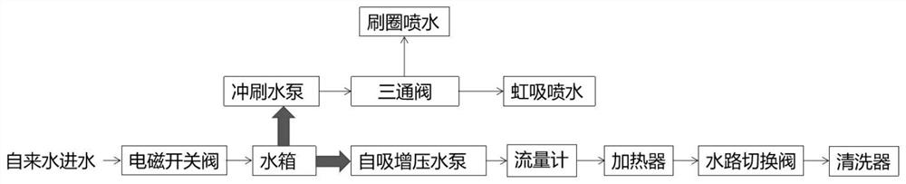
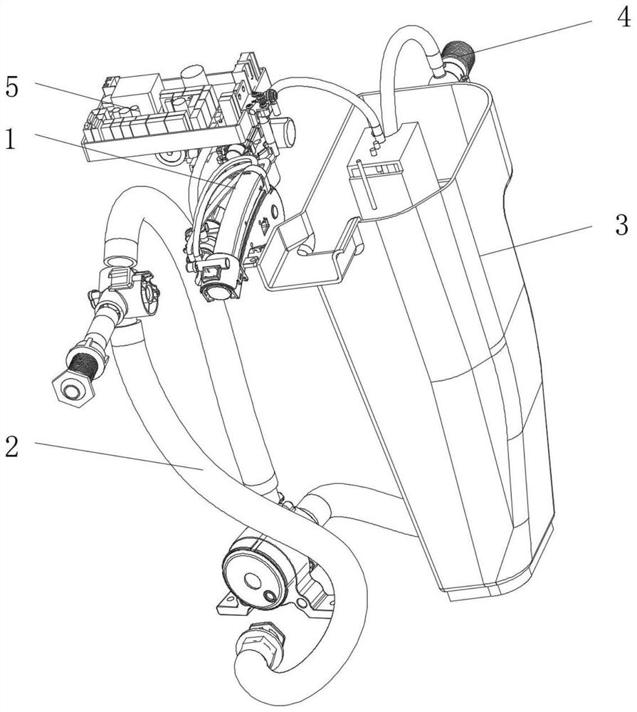
[0026] like Figure 2 to Figure 4 As shown, the smart toilet water circuit system of this embodiment includes a cleaning water circuit 1 and a flushing water circuit 2. The difference from the existing water circuit structure is that the two are no longer independent water circuits for taking water from the water source, but are passed through by the water tank 3. The valve body 4 is connected to the water source, and the access ends of the cleaning water channel 1 and the flushing water channel 2 are connected to the water tank 3. In this setting, the overlapping part of the two water channels is set as a common part, so as to avoid too many components and connections caused by independent settings. The problems of cumbersomeness, complex control, high production cost and large space occupation reduce the complexity of control logic, save more hardware and software system control resources, save more internal structure space, and ultimately reduce product cost. And because th...


PUM


Abstract

The water path system comprises a cleaning water path and a flushing water path and further comprises a water tank, the water tank is connected with a water source through a valve body, the connecting-in ends of the cleaning water path and the flushing water path are both connected to the water tank, and the cleaning water path comprises a first water pump and a cleaner; the cleaning waterway takes water from the water tank through the first water pump and supplies the water to the cleaner at the tail end of the waterway. The water path system for the intelligent closestool has the advantages that the structural arrangement is reasonable, logic components are simplified, the occupied space is reduced, and the cleaning water pressure is guaranteed.

Description

technical field [0001] The invention relates to the technical field of intelligent toilet structures, in particular to an intelligent toilet water circuit system. Background technique [0002] In the existing smart toilet, the ceramic flushing waterway and the human body washing waterway are set separately, and are respectively connected to tap water, and each waterway component is independent of each other, so the connection operation is relatively cumbersome, and the production and maintenance costs are also high. In the human body cleaning waterway of a general smart toilet, such as figure 1 As shown in the figure, the valve body with electromagnetic switch, decompression, and air isolation functions is connected to the tap water pipeline, and the back end is also connected to the flow meter, pressure reducing valve, heater, anti-siphon structure, water distribution flow regulating valve and other structures Only then can it be finally connected to the washer, and water ...

Claims


Application Information

Patent Timeline
Patent Type & Authority Applications(China)
IPC IPC(8): E03D9/08E03D1/00E03D1/38
CPCE03D9/08E03D1/00E03D1/38
Inventor 邱鹏飞刘瑞王林江
Owner HUNAN MEGMEET ELECTRICAL TECH CO LTD
Why Eureka
Try Eureka