Combined multifunctional accessory of grouting sleeve for steel bar connection and combined use method
A grouting sleeve and combined technology, which is applied in the direction of building components, building reinforcements, buildings, etc., can solve the problems of easy deformation of sealing accessories, discontinuous building materials, insufficient support strength, etc., and achieve good connection strength and light weight , good support strength
- Summary
- Abstract
- Description
- Claims
- Application Information
AI Technical Summary
Problems solved by technology
Method used
Image
Examples
Embodiment 1
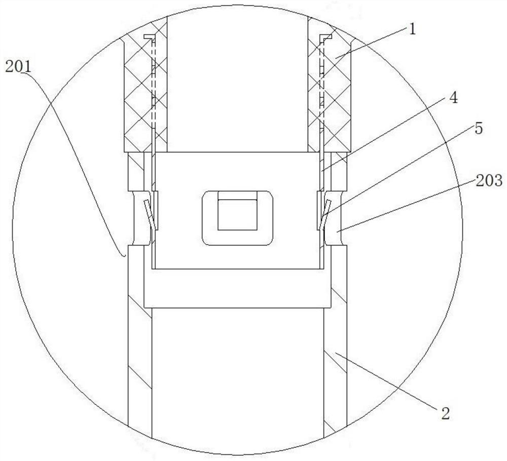
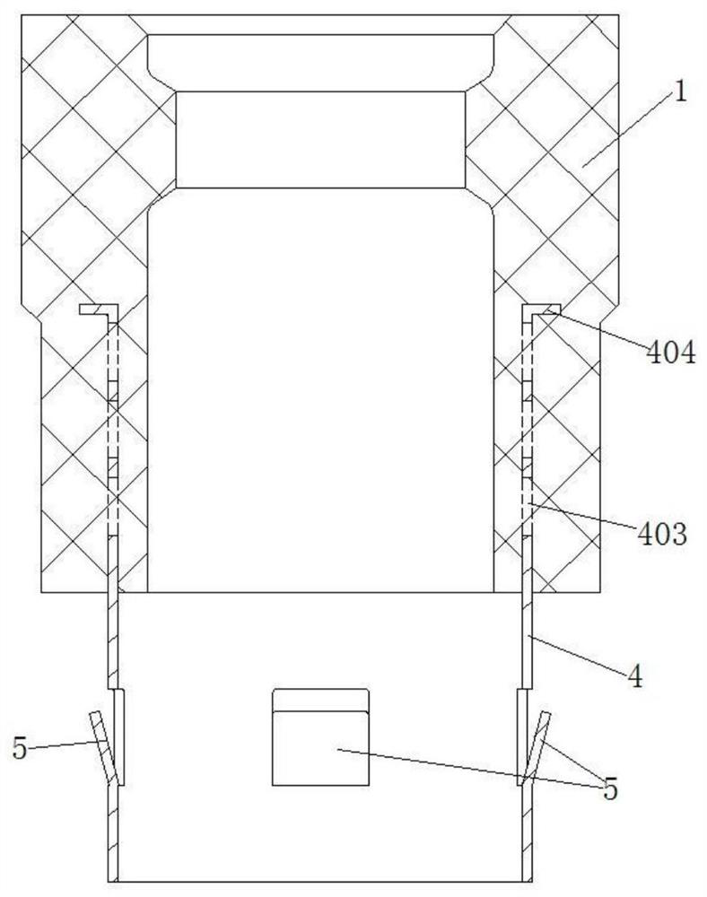
[0041] like figure 1 and figure 2 As shown, a combined multifunctional accessory for a grouting sleeve for steel bar connection includes a combined rubber plug 1, an intermediate cylinder part 2 and a rubber cylinder 3; the rubber plug 1 is close to the intermediate cylinder part 2 is provided with a metal bushing 4 in one end, and the exposed part of the metal bushing 4 is provided with a plurality of buckles 5 and is fitted and sleeved in the first end 201 of the middle cylinder part 2; the rubber One end of the column 3 close to the middle column part 2 is provided with a boss 6, and the boss 6 is screwed into the second end 202 of the middle column part 2; the end sleeve where the rubber column 3 is located A positioning screw 7 with a pressing retaining ring 8 is provided. The positioning screw 7 penetrates the rubber column 3 and the boss 6 and extends into the interior of the middle cylinder part 2. The positioning screw 7 is exposed. The partially removable sleeve i...
Embodiment 2
[0057] This embodiment provides a method for using the multifunctional accessory in the first embodiment in cooperation with the grouting sleeve.
[0058] like Figure 5 As shown, the multifunctional accessory is provided in the grouting sleeve 11 , the grouting sleeve 11 has a grouting port 13 and a grouting port 12 , and the middle cylinder portion 2 is sleeved in the grouting sleeve 11 and maintain a gap with the inner wall of the grouting sleeve 11 , the first end 201 is located on one side of the grouting port 12 , and the second end 202 is located on one side of the grouting port 13 ; The grouting sleeve 11 is placed on the end plate 14 of the preform template, the lower end of the positioning screw 7 protrudes from the lower end of the grouting sleeve 11, and a gasket is inserted into the exposed part of the positioning screw 7 9 and locknut 10.
[0059] like Image 6 As shown, the locking nut 10 is locked so that the positioning screw 7 generates a downward pressure...
PUM
 Abstract
Description
Claims
Application Information
 - R&D
- Intellectual Property
- Life Sciences
- Materials
- Tech Scout
- Unparalleled Data Quality
- Higher Quality Content
- 60% Fewer Hallucinations
Browse by: Latest US Patents, China's latest patents, Technical Efficacy Thesaurus, Application Domain, Technology Topic, Popular Technical Reports.
© 2025 PatSnap. All rights reserved.Legal|Privacy policy|Modern Slavery Act Transparency Statement|Sitemap|About US| Contact US: help@patsnap.com


