Steel bar mechanical connecting device

A technology of mechanical connection and reinforcement, which is applied in the processing of building materials, construction, building reinforcements, etc. The position cannot be adjusted, etc., to achieve the effect of intuitive and convenient quality inspection, easy construction quality assurance, and simple structure

Pending Publication Date: 2022-07-15
CENT RES INST OF BUILDING & CONSTR CO LTD MCC GRP +1
View PDF0 Cites 2 Cited by
  • Summary
  • Abstract
  • Description
  • Claims
  • Application Information

AI Technical Summary

Problems solved by technology

[0003]When the steel bars at both ends are fixed and cannot be rotated, and the axial relative position of the two steel bars cannot be adjusted or the adjustment is difficult, usually the extension wire head and the through button sleeve are used on site To connect, the through-buckle sleeve is first screwed on one end of the steel bar extension wire, and the end of the sleeve is flush with the end of the wire head. The steel wire heads are processed separately. It is very common that the helical tracks of the two ends of the steel wire heads cannot be overlapped when they are placed randomly. Therefore, when the through button sleeve is turned to the other end of the steel wire head, the The helical trajectories do not overlap and the sleeve cannot be screwed to the steel wire head at the other end, or the through-buckle sleeve and the steel wire head cannot reach the specified length position, resulting in the failure of the connection operation

Method used


Image

  • Steel bar mechanical connecting device
  • Steel bar mechanical connecting device
  • Steel bar mechanical connecting device

Examples


Embodiment Construction

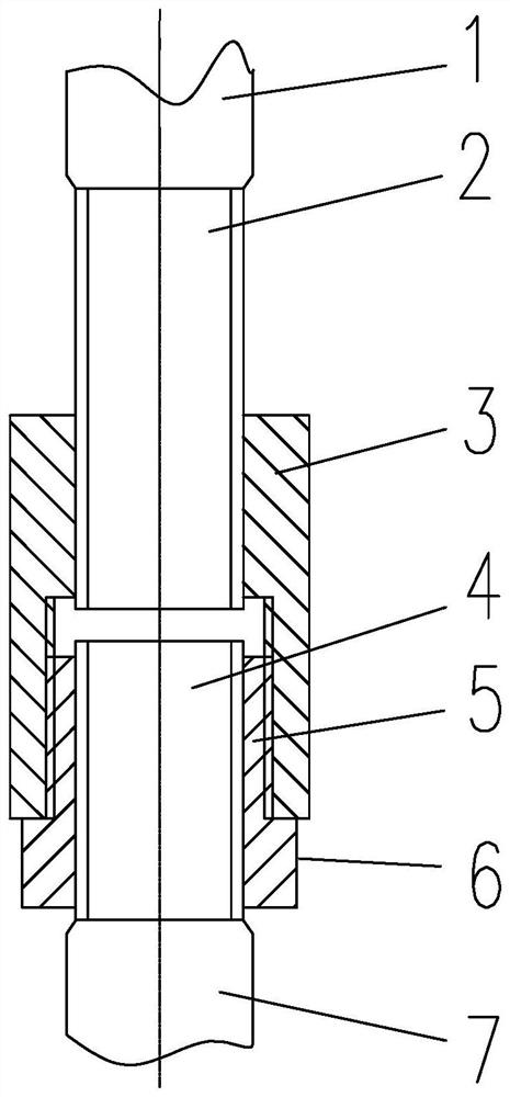
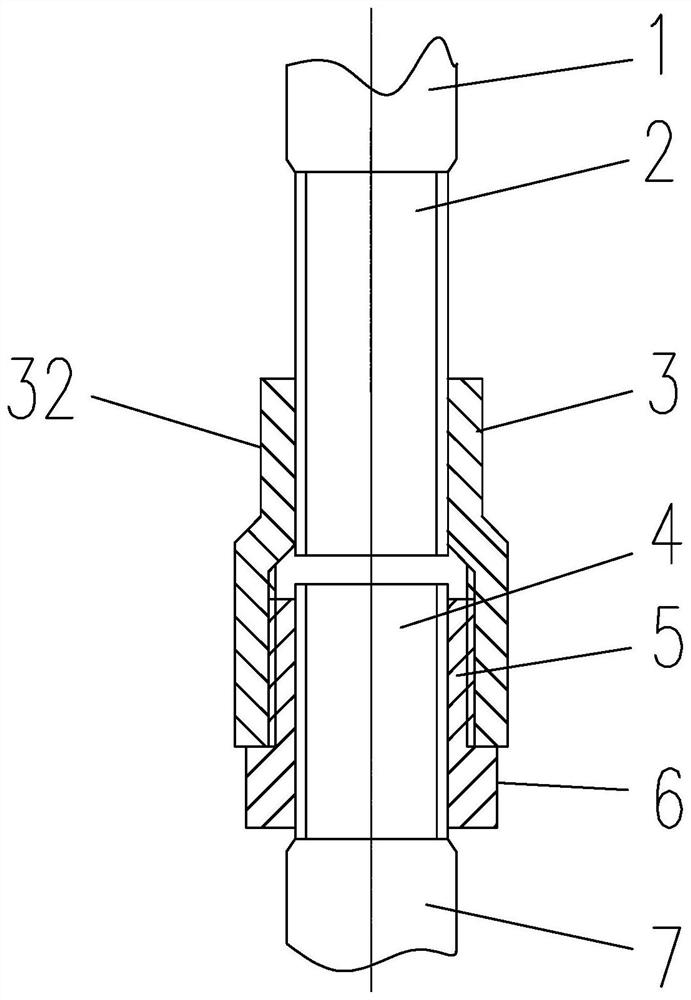
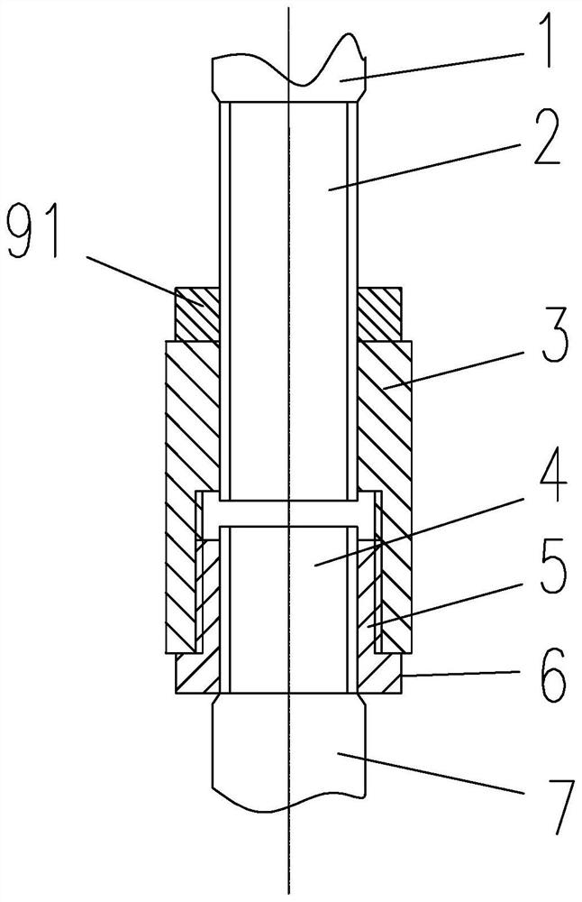
[0026] like figure 1 As shown, the present invention provides a mechanical connecting device for reinforcing bars, which is used to connect a first reinforcing bar 1 and a second reinforcing bar 7 arranged oppositely. The end of the steel bar is processed with a steel wire head 4; the steel mechanical connection device includes a screw sleeve 5 and a connecting sleeve 3, and the inner thread of the screw sleeve 5 can form a second threaded connection with the steel wire head 4 of the second steel bar 7, and the connection The inner thread of one end of the sleeve 3 can form a first threaded connection with the elongated steel wire head 2 of the first reinforcing bar 1, and the inner thread of the other end of the connection sleeve 3 can form a third threaded connection with the outer thread of the screw sleeve 5;

[0027] Wherein, a shoulder 6 is formed at one end of the screw sleeve 5 close to the second steel bar 7 .

[0028] Before the steel bars are docked in place, first...


PUM


Abstract

The invention provides a reinforcing steel bar mechanical connecting device which is used for connecting a first reinforcing steel bar and a second reinforcing steel bar which are oppositely arranged, a lengthened reinforcing steel bar wire head is machined at the end of the first reinforcing steel bar, and a reinforcing steel bar wire head is machined at the end of the second reinforcing steel bar. The reinforcing steel bar mechanical connecting device comprises a threaded sleeve and a connecting sleeve, an internal thread of the threaded sleeve and a reinforcing steel bar wire head of a second reinforcing steel bar can form second threaded connection, and an internal thread at one end of the connecting sleeve and a lengthened reinforcing steel bar wire head of a first reinforcing steel bar can form first threaded connection. The internal thread at the other end of the connecting sleeve can form third threaded connection with the external thread of the threaded sleeve; a protruding shoulder is formed at the end, close to the second steel bar, of the threaded sleeve. According to the invention, a larger thread pair axial adjusting gap is formed by three pairs of matched threads, so that the probability of superposition of spiral tracks is greatly improved, and the connection of reinforcing steel bars becomes very convenient and rapid.

Description

technical field [0001] The invention relates to a mechanical connecting device for steel bars. Background technique [0002] When the steel bars of concrete buildings are connected, the sleeve straight thread connection method is often used. Mechanical connection. [0003] When the steel bars at both ends are fixed and cannot be rotated, and the relative axial position of the two steel bars cannot be adjusted or is difficult to adjust, the extension wire head and the through-buckle sleeve are usually used on site to connect, and the through-buckle sleeve is first screwed on one end of the steel extension wire head. , the end of the sleeve is flush with the end of the wire head, when the butt connection is made, the sleeve is twisted to the other end of the steel wire head. It is very common that the helical trajectories of the steel wire heads at both ends cannot overlap, so when the through-buckle sleeve rotates to the other end of the steel wire head, the sleeve cannot b...

Claims


Application Information

Patent Timeline
Patent Type & Authority Applications(China)
IPC IPC(8): E04G21/12E04C5/16
CPCE04G21/122E04C5/16E04C5/165
Inventor 钱冠龙郭耀斌朱清华郝志强王爱军祝岩蔡英杰程亮郝敏郭学友牟顺利谢松方正李建坤
Owner CENT RES INST OF BUILDING & CONSTR CO LTD MCC GRP
Why Eureka
Try Eureka