
LED lamp tube power-on detection device and detection method

A technology of LED lamp tube and detection device, applied in the direction of measurement device, measurement device shell, lamp testing, etc., can solve the problems of incomplete detection, underutilization, waste of time, etc., and achieve convenient removal, loading, installation, and power-on time. Long and good detection effect

Active Publication Date: 2022-07-15
JIAGNSU PUYA LIGHTING TECH PUBLIC CO LTD
View PDF11 Cites 5 Cited by
  • Summary
  • Abstract
  • Description
  • Claims
  • Application Information

AI Technical Summary

Problems solved by technology

[0003] The traditional lamp inspection is to insert the lamp into the lamp holder, and then power on for inspection. If the light is on, the product is qualified, take out the lamp, and replace the lamp to be tested with electricity for inspection. This inspection method is not comprehensive and has no guarantee. The power-on time of the lamp tube is long enough, and there is uncertainty. At the same time, the lamp tube detection is generally carried out in batches. This method often requires manual installation and power-on of the lamp tube, and then the detection time period, which is not available. If it is fully utilized, if the detection time is long enough, more time will be wasted, and the detection efficiency of the lamp cannot be improved.

Method used


Image

  • LED lamp tube power-on detection device and detection method
  • LED lamp tube power-on detection device and detection method
  • LED lamp tube power-on detection device and detection method

Examples


Embodiment 1

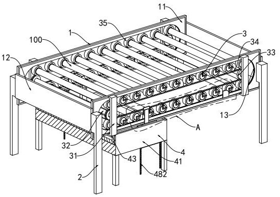
[0041] see figure 1 , an LED lamp power-on detection device disclosed in this embodiment includes a detection frame 1 and a support leg 2 for supporting and fixing the detection frame 1. The detection frame 1 includes two front and rear guide rail frames 11, two The two ends of the guide rail frame 11 are connected and fixed by two connecting plates 12 respectively. The guide rail frame 11 is provided with a running track 13 , and the running track 13 is provided with a running detection mechanism 3 .

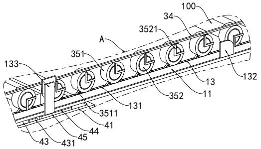
[0042] The operation detection mechanism 3 includes mounting brackets 31 installed on both ends of the guide rail frame 11 , a rotating shaft 32 is installed between the two symmetrical mounting brackets 31 through bearings, and both ends of the rotating shaft 32 are installed through bearings. Linkage sprocket 33, the two linkage sprockets 33 located on the same guide rail frame 11 are connected by a transmission chain 34, and a plurality of clamping energization units are con...

Embodiment 2

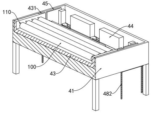
[0053] see image 3 , Figure 4 , Figure 5 , Figure 7 and Figure 8 , on the basis of the first embodiment, in order to ensure that the lamp 100 can be automatically loaded without manual clamping, installation and power-on detection of the lamp 100, an automatic feeding mechanism 4 is arranged under the detection frame 1, so The automatic feeding mechanism 4 includes a feeding bottom frame 41 installed with support bars, a feeding slot 42 is opened on the right side of the bottom of the feeding bottom frame 41, and a transportation platform 43 is provided on the left side of the bottom of the feeding bottom frame 41. , and the right end of the transport platform 43 is located above the feeding chute 42. The feeding chute 42 is provided with a rectangular pre-clamping frame 44 with an open upper end, and the rectangular pre-clamping frame 44 is distributed on the front and rear sides of the feeding chute. 42 There are gap areas 45 on both the front and rear sides, cavity...


PUM


Abstract

The invention relates to the technical field of LED lamp tube power-on detection, in particular to an LED lamp tube power-on detection device and method.The LED lamp tube power-on detection device comprises a detection frame and supporting legs used for supporting and fixing the detection frame, the detection frame comprises two guide rail frames distributed front and back, and the two ends of the two guide rail frames are connected and fixed through two connecting plates; a running track is arranged on the guide rail frame, a running detection mechanism is arranged in the running track, and an automatic feeding mechanism is arranged below the detection frame. According to the invention, the plurality of clamping electrifying units can be driven to move in the operation track through the transmission chain, so that electrifying detection can be carried out on a plurality of to-be-detected lamp tubes at the same time, the electrifying time of the lamp tubes can be ensured to be long enough, and a better detection effect is achieved; according to the automatic feeding and electrifying device for the lamp tube, the lamp tube to be detected can be automatically corrected, clamped and pushed into the detection frame, manual feeding and electrifying of the lamp tube are not needed, and the automatic feeding function and the automatic electrifying function of the lamp tube are achieved.

Description

technical field [0001] The invention relates to the technical field of energization detection of LED lamps, in particular to a detection device and detection method for energization of LED lamps. Background technique [0002] With the development of economy, the increasingly severe energy and environmental problems have become the focus of attention. Compared with traditional lighting sources, LED lamps have the advantages of environmental protection, energy saving and long life, and have gradually replaced traditional lighting sources as the main lighting source. In order to ensure product quality, LED lights need to be tested during the production process to check whether each LED light is normally illuminated under power. [0003] The traditional lamp inspection is to insert the lamp into the lamp holder, and then power on the test. If the light is on, the product is qualified, take out the lamp, and replace the lamp to be tested. The test is not comprehensive, and there...

Claims


Application Information

Patent Timeline
Patent Type & Authority Applications(China)
IPC IPC(8): G01R31/44G01R1/02G01R1/04
CPCG01R31/44G01R1/02G01R1/0425Y02B20/40
Inventor 钟婵
Owner JIAGNSU PUYA LIGHTING TECH PUBLIC CO LTD
Learn More