
Hardware punching machine with waste collecting mechanism

A metal stamping machine and waste collection technology, applied in the field of stamping machines, can solve the problems of single processing components, the inability to uniformly clean and recycle waste materials, and the inability to replace die head stamping as needed, and achieve the effect of improving service life and improving work efficiency.

Pending Publication Date: 2022-07-19
泰兴市凯力特弹簧有限公司
View PDF0 Cites 0 Cited by
  • Summary
  • Abstract
  • Description
  • Claims
  • Application Information

AI Technical Summary

Problems solved by technology

[0004] The object of the present invention is to provide a metal stamping machine with a waste collection mechanism in view of the deficiencies of the prior art, which solves the problem of immobilization of stamping dies and single processing components, that is, it is impossible to replace different types of die heads for stamping as required, and During the working process, the waste generated by processing cannot be cleaned and recycled uniformly

Method used


Image

  • Hardware punching machine with waste collecting mechanism
  • Hardware punching machine with waste collecting mechanism
  • Hardware punching machine with waste collecting mechanism

Examples


Embodiment Construction

[0027] The present invention will be further described below with reference to the accompanying drawings and embodiments.

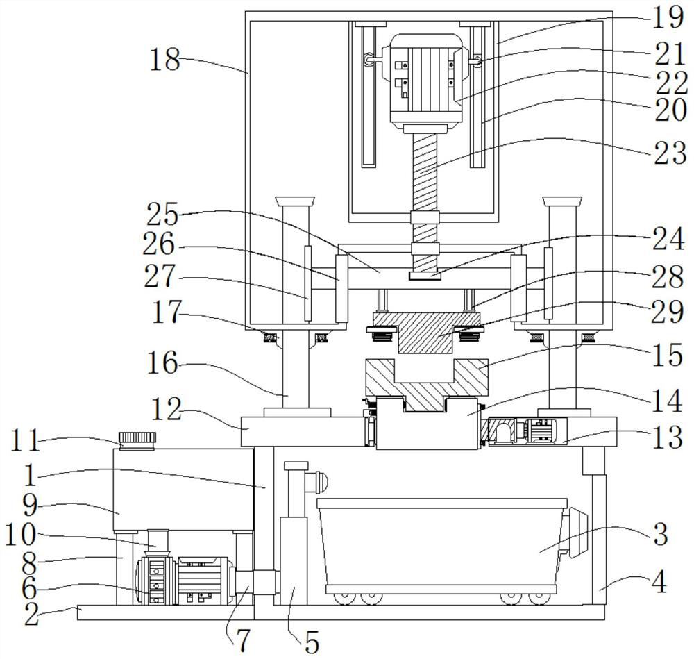
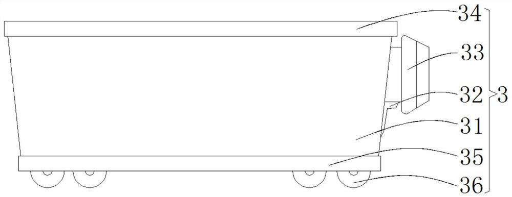
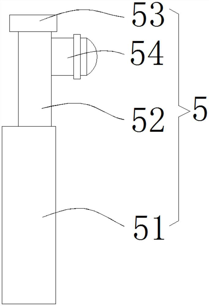
[0028] Please refer to figure 1 , figure 2 , image 3 , Figure 4 , Figure 5 , Image 6 , Figure 7 , Figure 8 and Figure 9 ,in, figure 1 A schematic structural diagram of a preferred embodiment of a metal stamping machine with a waste collection mechanism provided by the present invention; figure 2 for figure 1 The schematic diagram of the structure of the waste collection device shown; image 3 for figure 1 Schematic diagram of the structure of the cleaning rod shown; Figure 4 for figure 1 Schematic diagram of the structure of the rotary pouring device shown; Figure 5 for figure 1 The schematic structural diagram of the stamping die fixing device shown; Image 6 for Figure 5 The enlarged schematic diagram of Part A shown; Figure 7 for Figure 5 The enlarged schematic diagram of part B shown; Figure 8 for figure 1 Schematic...


PUM


Abstract

The hardware punching machine with the waste collecting mechanism comprises a machine base box, a waste collecting device is placed in the punching machine base box, a cleaning rod is arranged on the left side in the punching machine base box, a punching work bottom plate is arranged on the upper surface of the punching machine base box, and a rotary material pouring device is arranged in the right side part of the punching work bottom plate. According to the hardware punching machine with the waste collecting mechanism, waste generated in the punching machining process can be dumped in time, the waste is recycled, a machine table does not need to be cleaned again, the waste collecting mechanism is simple in structure and convenient to operate, the cost is reduced, and the hardware punching machine with the waste collecting mechanism is suitable for popularization and application. According to the stamping device, the working pressing table can be cleaned while waste materials are recycled, the service life of the device is prolonged, the die plate and the stamping head can be very conveniently replaced when different types of dies are stamped according to needs, and the working efficiency is greatly improved.

Description

technical field [0001] The present invention particularly relates to a punching machine. Background technique [0002] Stamping is a forming and processing method that relies on presses and dies to apply external forces to sheets, strips, pipes and profiles to produce plastic deformation or separation, thereby obtaining workpieces of the required shape and size. The power of the stamping equipment causes the sheet metal to be directly deformed and deformed in the mold, so as to obtain the production technology of product parts with a certain shape, size and performance. [0003] At present, most of the stamping devices on the market have fixed stamping dies and single processing components, that is, it is impossible to replace different types of die heads for stamping as needed, and during the working process, the waste generated by processing cannot be cleaned and recycled uniformly. SUMMARY OF THE INVENTION [0004] The object of the present invention is to provide a me...

Claims


Application Information

Patent Timeline
IPC IPC(8): B21D37/10B21D37/14B21D43/20
CPCB21D37/10B21D37/14B21D43/20Y02P70/10
Inventor 朱榴陆健蒋菠萝
Owner 泰兴市凯力特弹簧有限公司
Learn More