Joint debugging mechanism and sewing machine

A sewing machine and joint debugging technology, which is applied in the direction of sewing machine components, cloth pressing mechanism, sewing equipment, etc., can solve the problems of unfavorable sewing machine miniaturization and low-cost development

Pending Publication Date: 2022-07-19
JACK SEWING MASCH CO LTD
View PDF0 Cites 0 Cited by
  • Summary
  • Abstract
  • Description
  • Claims
  • Application Information

AI Technical Summary

Problems solved by technology

[0004] The presser foot lifting mechanism and the presser foot pressure adjustment mechanism in the existing sewing machine structure are generally adjusted by a separate driving source, and multiple driving sources are installed in the sewing machine at the same time, which is not conducive to the development of the sewing machine in the direction of miniaturization and low cost.

Method used


Image

  • Joint debugging mechanism and sewing machine
  • Joint debugging mechanism and sewing machine
  • Joint debugging mechanism and sewing machine

Examples


Embodiment 1

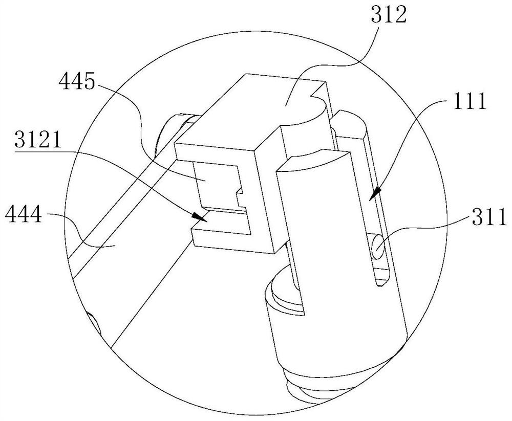
[0074] see image 3 , image 3 for figure 2 An enlarged schematic view at A of the sewing machine 100 is shown.

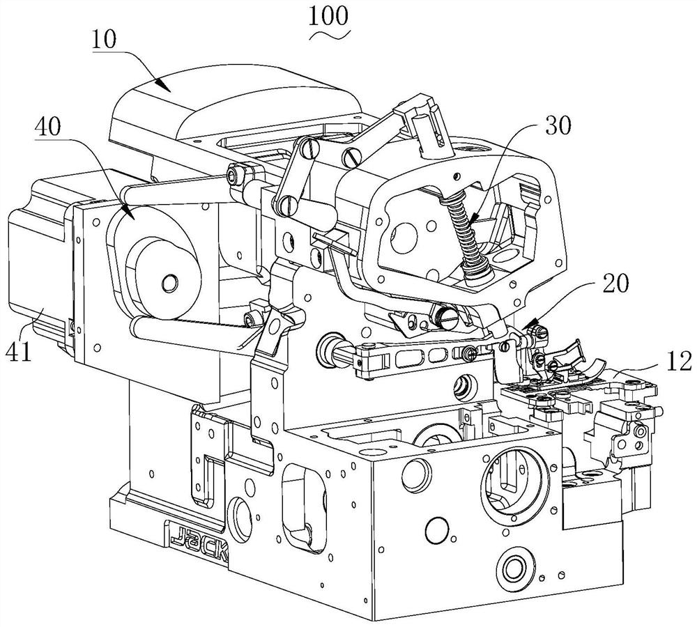
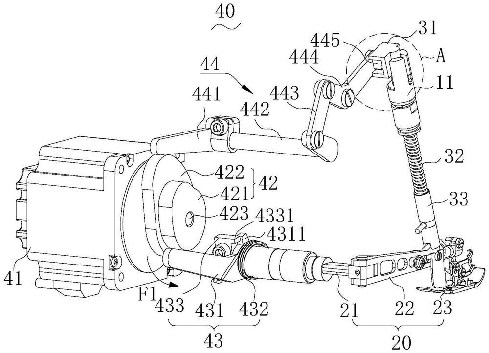
[0075] like figure 1 and figure 2As shown, the joint adjustment mechanism 40 includes a driving source 41 , a driving element 42 , a first driving component 43 and a second driving component 44 . The driving element 42 is connected to the output end of the driving source 41; the first driving element 43 and the second driving element 44 are respectively connected to different areas of the driving element 42, and the first driving element 43 is connected to the presser foot shaft of the presser foot lifting mechanism 20 21. The second drive assembly 44 is correspondingly connected to the pressure regulating elastic member 32 of the presser foot pressure regulating mechanism 30 . The driving element 42 is used to output power to the first driving component 43 and the second driving component 44, and control the first driving component 43 and the second driving...

Embodiment 2

[0114] Please also refer to Figures 6 to 9 , Image 6 It is a schematic structural diagram of the joint adjustment mechanism 40 and other mechanisms of the sewing machine 100 according to another embodiment of the present invention; Figure 7 for Image 6 The illustrated sewing machine 100 is a schematic structural diagram of another perspective after some components are omitted; Figure 8 for Image 6 A schematic diagram of the structure of the drive element 42a in the sewing machine 100 shown; Figure 9 for Figure 8 A schematic diagram of the rotation area of ​​the driving source 41 corresponding to the functional area of ​​the driving element 42a shown.

[0115] The difference from the above-mentioned embodiment is the arrangement of the driving element 42a, and the first driving element 43a and the second driving element 44a are correspondingly adjusted to match the driving element 42a.

[0116] In this embodiment, the drive element 42a is a cam assembly. The cam ...

Embodiment 3

[0131] Please also refer to Figure 10 and Figure 12 , Figure 10 It is a schematic structural diagram of the joint adjustment mechanism 40 and other mechanisms of the sewing machine 100 according to another embodiment of the present invention; Figure 11 for Figure 10 A schematic diagram of the structure of the drive element 42b in the sewing machine 100 shown; Figure 12 for Figure 11 A schematic diagram of the rotation area of ​​the driving source 41 corresponding to the functional area of ​​the driving element 42b shown.

[0132] In the present embodiment, the drive element 42b is an integrally provided cam member. The output end of the drive source 41 is connected to the cam member. The difference from the above two embodiments is that the first area 4211 and the second area 4222 are correspondingly formed in different areas of the cam member, and the first empty area 42112 of the first area 4211 and the second empty area of ​​the second area 4222 are The row ar...


PUM


Abstract

The invention relates to a joint debugging mechanism and a sewing machine. The joint adjusting mechanism is used for adjusting a presser foot lifting mechanism and a presser foot pressure adjusting mechanism in the sewing machine, the joint adjusting mechanism comprises a driving source, a driving element, a first driving assembly and a second driving assembly, the first driving assembly is connected to the presser foot lifting mechanism, and the second driving assembly is connected to the presser foot pressure adjusting mechanism. Wherein the driving element is connected to the output end of the driving source and can rotate along with the driving source; the driving element comprises a first area and a second area, and the first area acts on the first driving assembly and drives the presser foot lifting mechanism to act; the second area acts on the second driving assembly and adjusts the pressure value of the presser foot pressure adjusting mechanism. The embodiment of the invention provides a joint debugging mechanism. Due to the arrangement of the joint debugging mechanism, the sewing machine can work accurately, and the development requirement for miniaturization is met.

Description

technical field [0001] The invention relates to the field of sewing equipment, in particular to a joint adjustment mechanism and a sewing machine. Background technique [0002] Existing sewing machines often include multiple motion mechanisms for realizing different functions, such as cloth feeding mechanism, presser foot mechanism, thread trimming mechanism, lubricating mechanism, etc. These mechanisms coordinate and cooperate to complete the complete sewing function of the sewing machine. [0003] In the sewing machine, the main function of the presser foot mechanism is to cooperate with the feed dog frame to complete the dragging of the fabric during the feeding process, and press the fabric during the sewing process to complete the sewing work smoothly, and lift the presser foot plate after the sewing is completed. , to carry out the action of taking or adding material. The presser foot mechanism further includes a presser foot lifter mechanism that presses down and lif...

Claims


Application Information

Patent Timeline
IPC IPC(8): D05B29/02
CPCD05B29/02
Inventor 林昌盛刘袁赵林蔚徐永明何礼会
Owner JACK SEWING MASCH CO LTD
Why Eureka
Try Eureka