Distraction device for oral and maxillofacial surgery

A technique for surgery and oral and maxillofacial surgery, applied in the field of retractors for oral and maxillofacial surgery, which can solve the problems of inconvenient adjustment of the range of retraction, inability to support the patient's upper and lower jaws, etc., and increase the area of ​​retraction , increased area, oral comfort effect

Inactive Publication Date: 2022-07-22
南阳市口腔医院
View PDF0 Cites 0 Cited by
  • Summary
  • Abstract
  • Description
  • Claims
  • Application Information

AI Technical Summary

Problems solved by technology

[0005] In order to overcome the above-mentioned disadvantages that the prior art cannot support the patient's maxilla and mandible, and it is inconvenient to adjust the range of distraction, the technical problem to be solved by the present invention is to provide a method that can support the patient's maxilla and mandible, and avoid A retractor for oral and maxillofacial surgery that can easily adjust the range of retraction if sharp objects cause damage to the patient's mouth

Method used


Image

  • Distraction device for oral and maxillofacial surgery
  • Distraction device for oral and maxillofacial surgery
  • Distraction device for oral and maxillofacial surgery

Examples


Embodiment 1

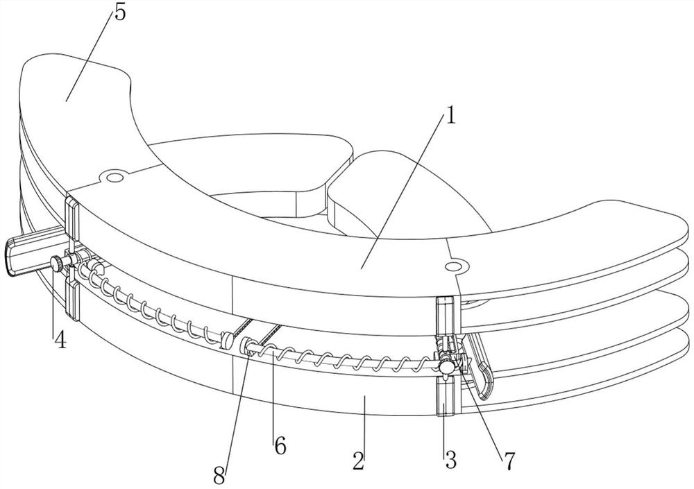
[0030] A spreader for oral and maxillofacial surgery, such as figure 1 , Figure 7 , Figure 8 and Figure 9 As shown, it includes a first cushion block 1, a second cushion block 2, a guide mechanism 3 and an up and down opening mechanism 4. The first cushion block 1 and the second cushion block 2 are arranged up and down, and the first cushion block 1 and the second cushion block are arranged up and down. A guide mechanism 3 is arranged between the cushion blocks 2 , and an upper and lower spreading mechanism 4 is arranged on the guide mechanism 3 .

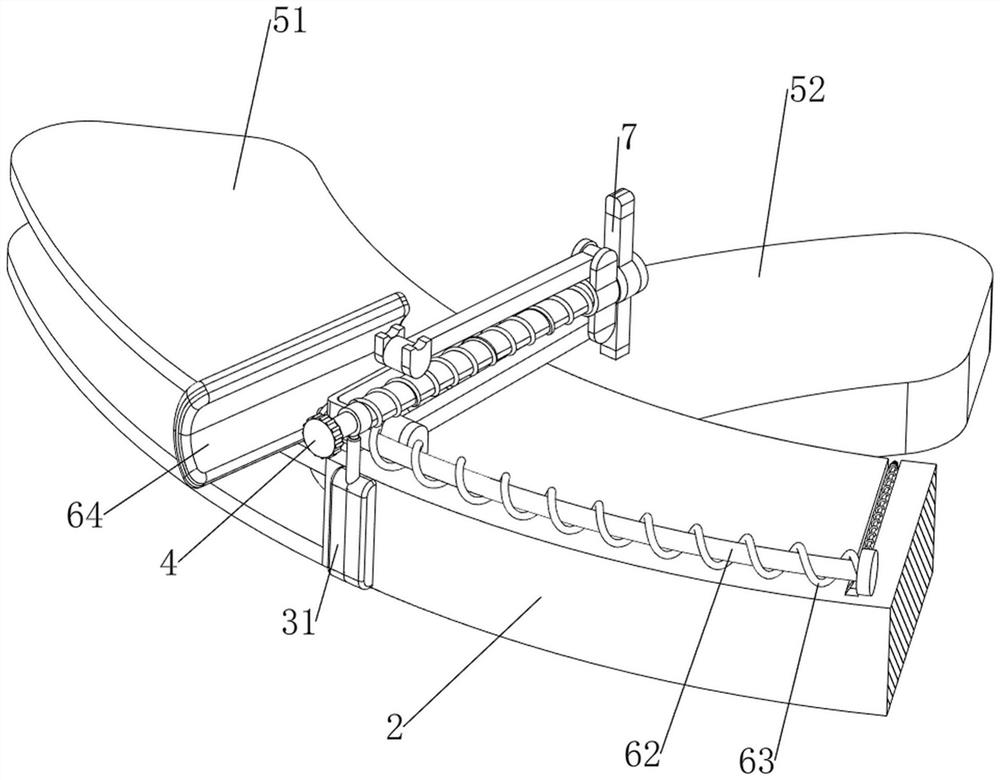
[0031] like Figure 8 and Figure 9 As shown, the guide mechanism 3 includes a mounting block 31, a sleeve 32, a guide rod 33 and a connecting ring 34. The front sides of the first cushion block 1 and the second cushion block 2 are bolted symmetrically with the mounting blocks 31. The mounting blocks A sleeve 32 is slidably provided on the sleeve 31 , a guide rod 33 is slidably provided on the sleeve 32 , and a connecting r...

Embodiment 2

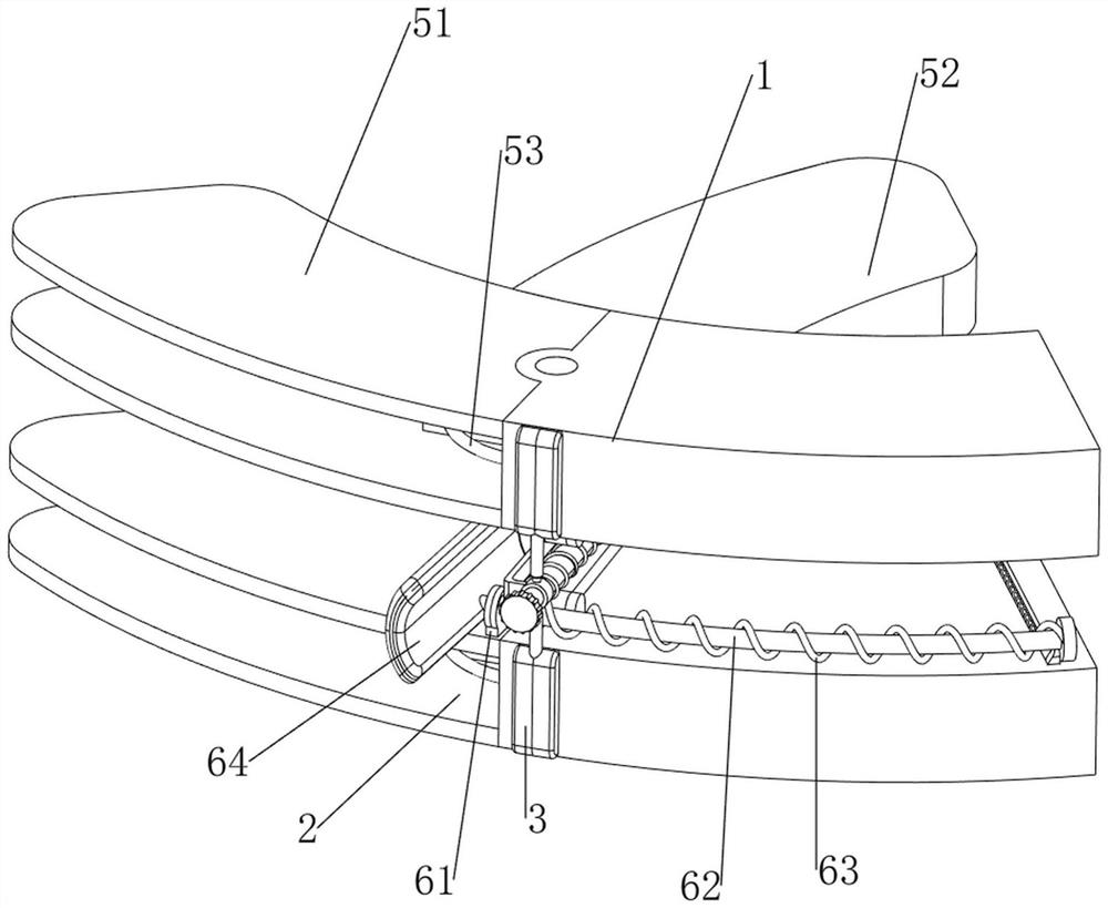
[0035] On the basis of Example 1, as figure 1 and figure 2 As shown, an expansion mechanism 5 is also included. The expansion mechanism 5 includes a silicone plate 51, a support block 52 and an elastic rope 53. The left and right sides of the first cushion block 1 and the second cushion block 2 are bolted symmetrically up and down with silicone Plate 51, the left and right sides of the first cushion block 1 and the second cushion block 2 are rotatably provided with support blocks 52, and the support blocks 52 on the upper and lower sides are respectively connected with the first cushion block 1 and the second cushion block 2. Elastic cord 53 for reset.

[0036] like figure 1 and Figure 7 As shown, it also includes a fixing mechanism 7. The fixing mechanism 7 includes a connecting plate 71, a fixing block 72 and a first rubber block 73. The connecting plate 71 is rotatably sleeved on the screw 41, and the upper and lower sides of the rear portion of the connecting plate 71...

Embodiment 3

[0039] On the basis of Example 2, as figure 1 , figure 2 and Figure 4 As shown, it also includes a side opening mechanism 6. The side opening mechanism 6 includes a guide block 61, a guide rod 62, a first return spring 63 and a support plate 64, and is connected to the second pad 2. On the silicone plate 51 above A guide block 61 is bolted on the side, a guide rod 62 is slidably penetrated on the guide block 61, and a clamping block is welded at one end of the guide rod 62 away from the guide block 61. On the outer side of the first return spring 63 , a support plate 64 is bolted to one end of the guide rod 62 close to the guide block 61 .

[0040] like figure 1 , Figure 5 and Image 6 As shown, it also includes a stretching mechanism 8. The stretching mechanism 8 includes a connecting block 81, a second rubber block 82, a pull rope 83, a second return spring 84 and a guide tube 85. Symmetrically open a chute, the rear side of the second spacer block 2 is bolted with ...


PUM


Abstract

The invention relates to a spreader, in particular to a spreader for oral and maxillofacial surgery. According to the dilator for the oral and maxillofacial surgery, the upper jaw and the lower jaw of a patient can be supported, the oral cavity of the patient can be prevented from being hurt by sharp objects, and the distraction range can be conveniently adjusted. The dilator for the oral and maxillofacial surgery comprises a first cushion block, a second cushion block, a guide mechanism, an up-down distraction mechanism and the like, the first cushion block and the second cushion block are arranged up and down, and the guide mechanism used for guiding is arranged between the first cushion block and the second cushion block. And the guide mechanism is provided with an up-down opening mechanism for assisting the opening of the oral cavity of the patient. The upper jaw and the lower jaw of a patient can be supported through the first cushion block and the second cushion block, the oral cavity of the patient can be prevented from being hurt by sharp objects, the opening range of the oral cavity of the patient can be conveniently adjusted by rotating the screw rod, and a doctor does not need to hold the oral cavity for a long time.

Description

technical field [0001] The invention relates to a spreader, in particular to a spreader for oral and maxillofacial surgery. Background technique [0002] In human medicine, oral and maxillofacial refers to a part of human organs, because it contains a wide range, such as lips, ears, nose and eyes, so we call it the face most of the time. When doctors perform oral and maxillofacial surgery, most of the patients' mouths are opened, so as to facilitate the observation of the inside of the patient's oral cavity. Most of them use tools such as pliers or clips to open the patient's mouth, which requires the doctor to hold the tool with force for a long time, so it is easy to cause the doctor's hand muscle soreness, and it is not convenient to control the distance of the mouth opening, so It is also easy to cause secondary injury to the patient. [0003] According to the patent authorization publication number CN214761247U and the announcement date of 20211119, a spreader for ora...

Claims


Application Information

Patent Timeline
Patent Type & Authority Applications(China)
IPC IPC(8): A61B1/24A61B90/16A61C19/00
CPCA61B1/24A61B90/16A61C19/00
Inventor 汤晓雨
Owner 南阳市口腔医院
Why Eureka
Try Eureka