Electric ball valve

A ball valve, electric technology, applied in the direction of valve details, valve devices, engine components, etc., can solve the problems of difficult disassembly and manufacturing, and achieve the effect of not easy to break down and easy to use

Inactive Publication Date: 2004-04-28
吴龙洙
View PDF0 Cites 2 Cited by
  • Summary
  • Abstract
  • Description
  • Claims
  • Application Information

AI Technical Summary

Problems solved by technology

This kind of valve drives the valve to rotate through multiple gears connected to the motor. Because the gears are installed inside the valve body, there are disadvantages such as difficult manufacturing and difficult disassembly when maintenance is required.

Method used


Image

  • Electric ball valve
  • Electric ball valve
  • Electric ball valve

Examples


Embodiment Construction

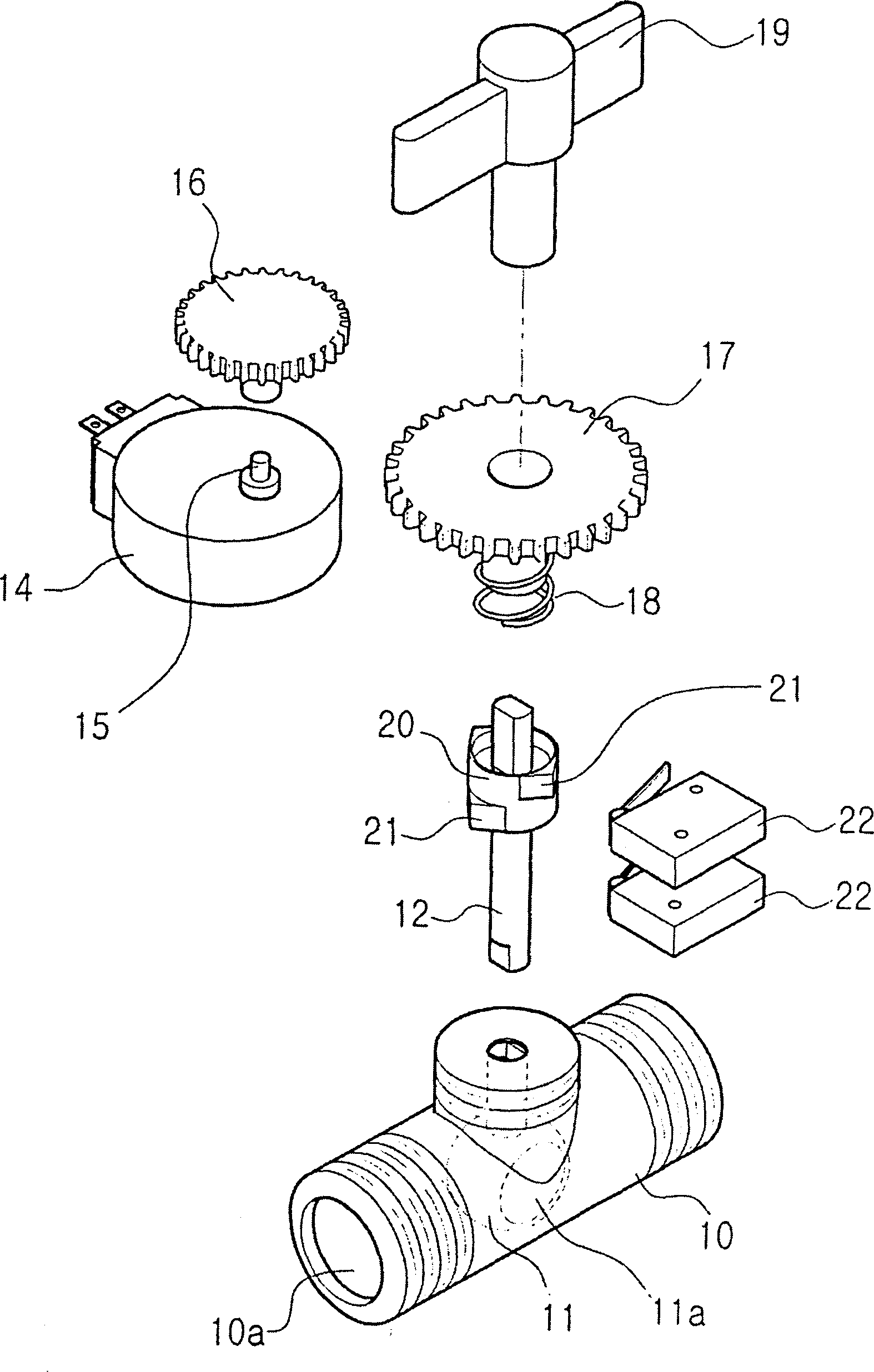
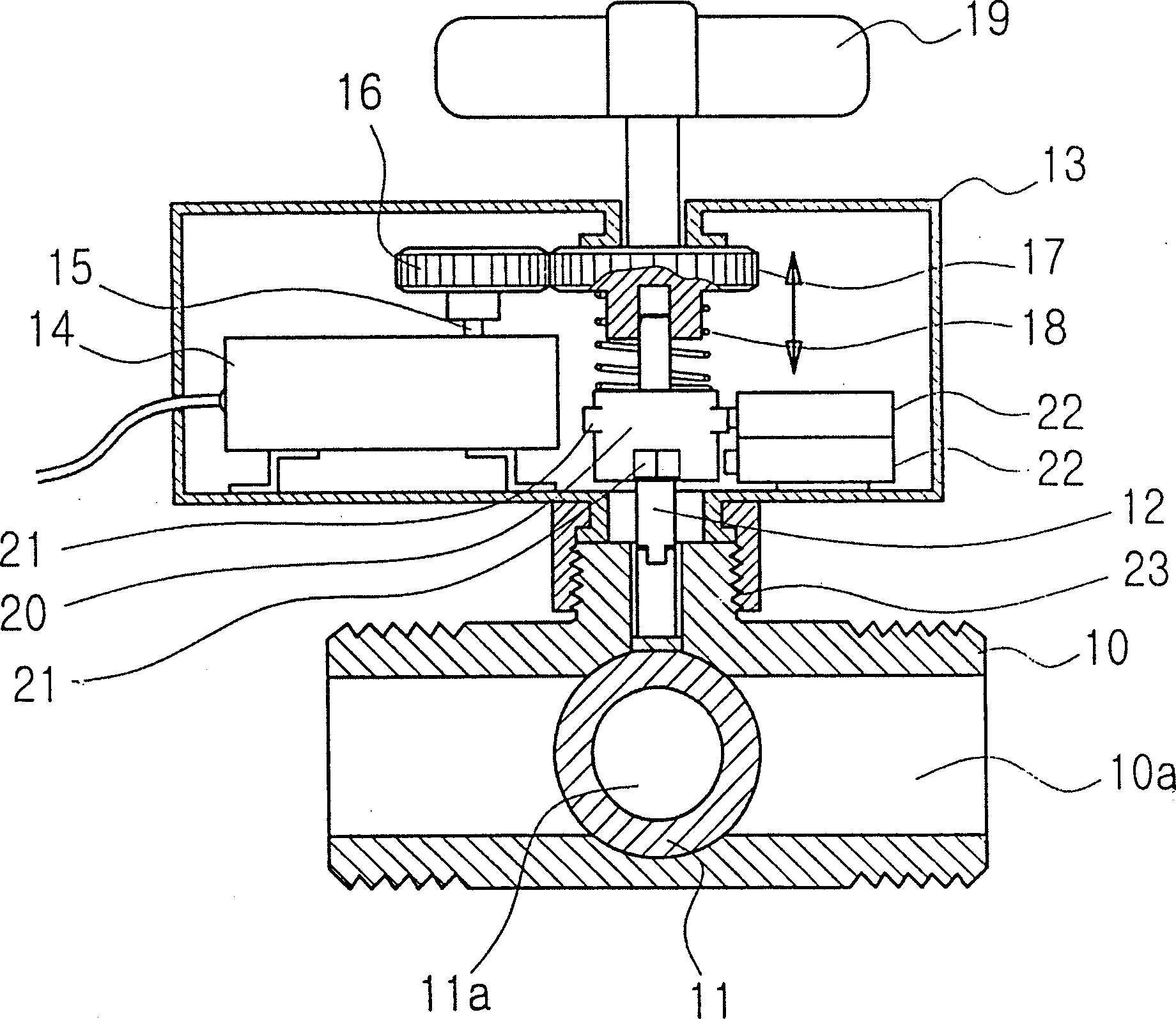
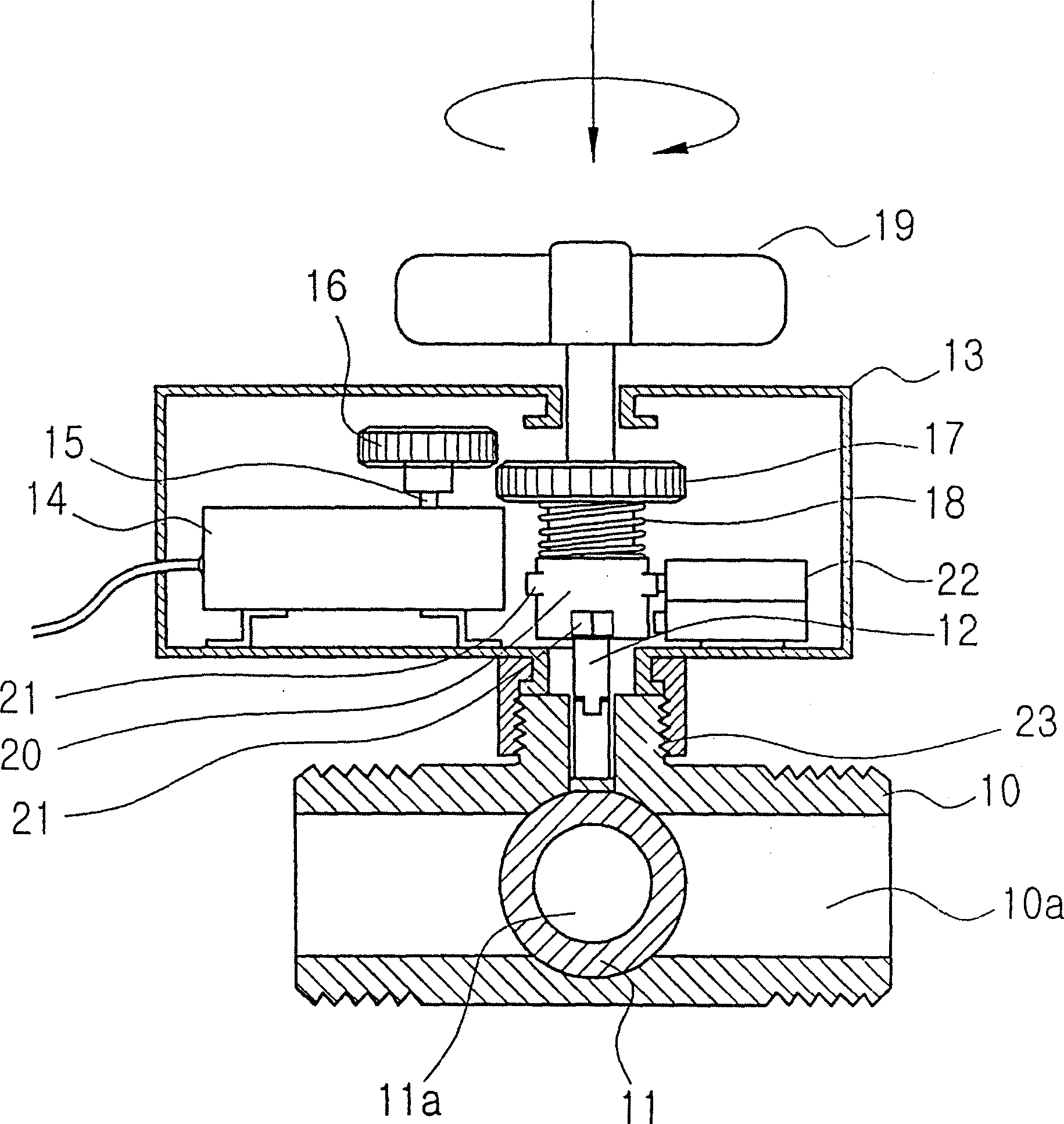
[0015] As can be seen from the drawings, the valve body 10 has a flow path 10a and a ball 11 for opening and closing the flow path 10a. The ball 11 is provided with a hole 11a in the same shape as the flow path 10a, and the valve is opened when the hole 11a is in the same direction as the flow path 10a.

[0016] The sphere 11 is connected to the rotating shaft 12 of the spherical valve. A cam 20 is arranged on the rotating shaft of the spherical valve. A plurality of bosses 2I are formed on the periphery of the cam 20 at intervals of 90 degrees. One side of the cam 20 is provided with a limit switch 22 that completes the on / off action by the boss 2I on the cam 20, and the other side of the cam is provided with a gear motor controlled by the limit switch 22 to rotate.

[0017] Synchronous Geared Motor 14, limit switch 22 and cam 20 are built in motor box 13, and motor box 13 is installed on the upper side of valve body 10, utilizes nut 23 and valve body 10 to connect. The moto...


PUM


Abstract

The present invention relates to an electromotion ball valve that rotates by the installation of a geared motor to thereby switch the passage thereof in an automatically operating manner and manipulates a manual lever to thereby switch the passage thereof in a manually operating manner, when the geared motor gets out of order or when the power is off, thereby achieving switching of the ball valve in an convenient manner. The electromotion ball valve has a valve body provided with a passage switching ball and a geared motor connected to the passage switching ball for automatically rotating a ball rotary shaft, which includes: a driving gear provided on a motor shaft of the geared motor; a driven gear provided on the ball rotary shaft and adapted to be engaged with the driving gear; a cam provided on the ball rotary shaft and forming a multistage protrusion on the outer periphery thereof; and a limit switch turned on and off by means of the protrusion and controlling the ball rotary shaft that rotates only in one direction by the geared motor to rotate the ball rotary shaft by 90°, for enabling the ball to switch a passage thereof.

Description

technical field [0001] The invention relates to a ball valve capable of opening and closing a flow path, in particular to an electric ball valve driven by a motor. Background technique [0002] Generally, spherical valves are manually operated, and are mostly used for hot water control or opening and closing of small-diameter pipes. There are many inventions to transform the above-mentioned manual spherical valve and make it become automatic, so as to reach the purpose of controlling the flow of hot water easily. Among them, Korean Utility Model Publication Publication No. 98-20262 introduces an automatic opening and closing valve device utilizing a solenoid valve device. This kind of valve connects the rotating shaft of the valve with the electromagnetic device, and converts the linear motion of the electromagnetic device into the rotary motion of the net, thereby opening and closing the valve. In this valve, because the linear motion of the electromagnetic device is too ...

Claims


Application Information

Patent Timeline
Patent Type & Authority Patents(China)
IPC IPC(8): F16K5/06F16K31/04F16K31/05F16K31/53
CPCF16K31/041F16K31/535F16K31/043F16K5/0647F16K37/0041
Inventor 吴龙洙
Owner 吴龙洙
Why Eureka
Try Eureka