Automatic maintenance device capable of being timed and lifted

A lifting pipe and control box technology is applied in the field of automatic maintenance devices that can be lifted and lowered regularly, and can solve the problems of maintenance scope and maintenance time that are difficult to meet standards, waste of labor and water resources, and concrete strength that cannot meet design requirements.

Active Publication Date: 2022-07-22
CHINA CONSTR THIRD ENG BUREAU GRP CO LTD
View PDF19 Cites 0 Cited by
  • Summary
  • Abstract
  • Description
  • Claims
  • Application Information

AI Technical Summary

Problems solved by technology

[0004] The use of artificial watering and maintenance not only caused a great waste of labor and water resources, but also caused the maintenance range and maintenance time to be difficult to meet the stand...

Method used


Image

  • Automatic maintenance device capable of being timed and lifted
  • Automatic maintenance device capable of being timed and lifted
  • Automatic maintenance device capable of being timed and lifted

Examples


Embodiment 1

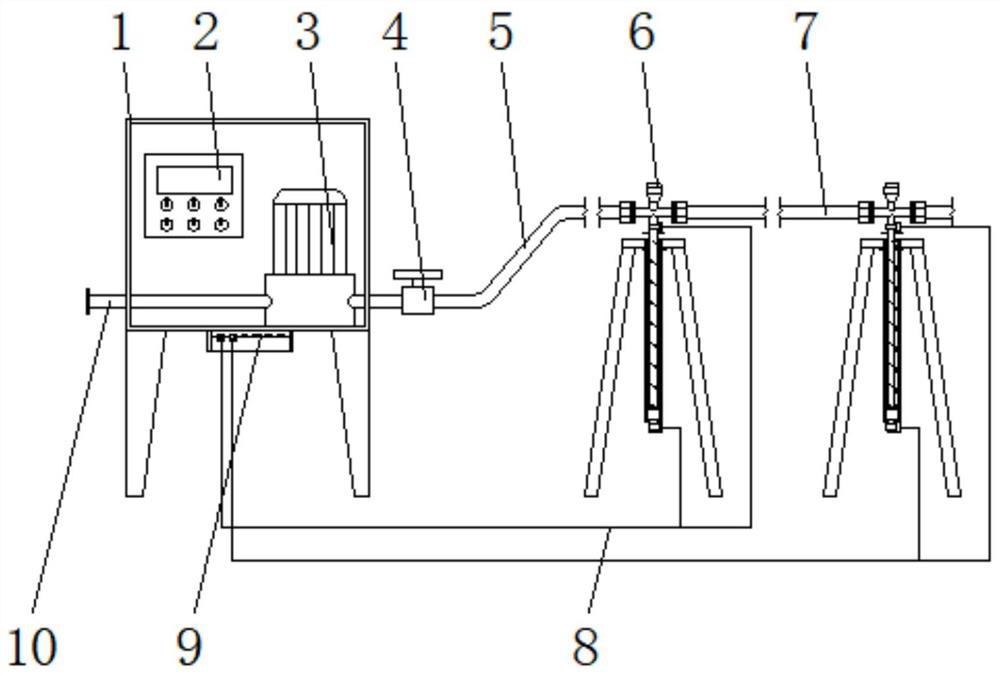
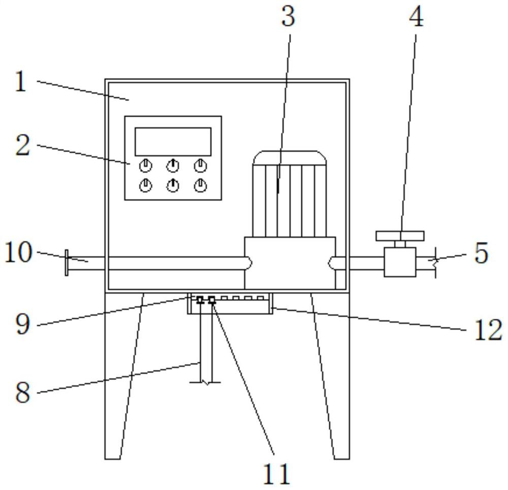
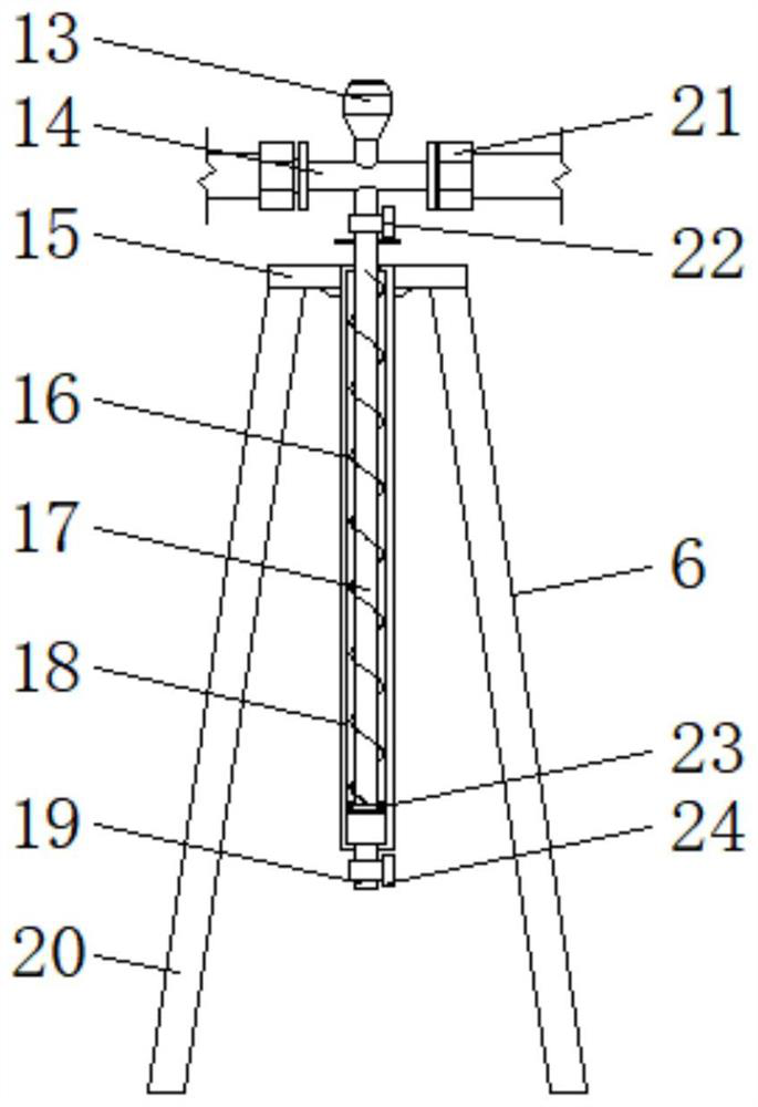
[0046]An automatic maintenance device that can be raised and lowered regularly, including a control box 1, a controller 2, a booster pump 3, a lifting spray frame 6, a plug board 9, a lifting pipe 17 and a casing 18. The maintenance device is composed of the control box 1 and the lifting and lowering The spray rack 6 is composed of a controller 2 and a booster pump 3 inside the control box 1. The elevating spray rack 6 is composed of a shunt pipe 14, an elevating pipe 17, a sleeve 18, a second solenoid valve 22 and a third solenoid valve 24. The controller 2 sets the power of the booster pump 3, which can realize the effect of timing and controlling the water pressure of the pump, so as to carry out the effect of water spray curing concrete for a specific time and a specific time period, and the second solenoid valve 22 can be operated at the same time. Manually controlled by personnel, the water in the lifting pipe 17 can be connected to the casing 18, and the lifting pipe 17 ...

Embodiment 2

[0049] A plug-in board 9 is installed at the bottom end of the control box 1, the second solenoid valve 22 and the third solenoid valve 24 are connected with a connecting wire 8, and the end of the connecting wire 8 is connected with a connector 11 that is adapted to the plug-in board 9, and the plug-in board 9 is connected to the controller 2, and the outer wall of the plug-in board 9 is provided with a baffle 12, the feedback circuit in the controller 2 can feed back the water pressure uploaded by the booster pump 3, and the controller 2 not only controls the operating power of the booster pump 3 and time, and also control the first solenoid valve 4, the second solenoid valve 22 and the third solenoid valve 24 respectively, so as to achieve the effect of flexible control.

Embodiment 3

[0051] One side of the booster pump 3 is connected to a drain pipe 5 penetrating the outer wall of the control box 1, the drain pipe 5 is connected to the elevating spray frame 6, and a communication pipe 7 is connected between the elevating spray frames 6, and the outer wall of the upper end of the sleeve 18 is welded with a The top plate 15, the lower surface of the top plate 15 is welded with support legs 20 distributed in a circular array, the lower end of the lifting pipe 17 is inserted into the inside of the sleeve 18, the bottom end of the lifting pipe 17 is welded with a travel plate 23, and the outer wall of the travel plate 23 is embedded and installed with a seal. The ring 26, the sealing ring 26 can seal between the travel plate 23 and the sleeve 18 to prevent water leakage and affect the normal movement of the lift pipe 17.

[0052] The bottom end of the sleeve 18 is provided with a pressure relief pipe 19, the outer wall of the pressure relief pipe 19 is provided ...


PUM


Abstract

The invention relates to a timed and liftable automatic maintenance device which comprises a control box, a controller, a booster pump, a lifting spraying frame, an inserting plate, a lifting pipe and a casing pipe, the maintenance device is composed of the control box and the lifting spraying frame, and the controller and the booster pump are arranged in the control box; the lifting spraying frame is composed of a flow dividing pipe, a lifting pipe, a sleeve, a second electromagnetic valve and a third electromagnetic valve. And one side of the booster pump is connected with a drainage pipe penetrating through the outer wall of the control box, the drainage pipe is connected with the lifting spraying frames, a communicating pipe is connected between the lifting spraying frames, and an inserting plate is installed at the bottom end of the control box. According to the automatic maintenance device, the method that lifting is achieved in a water pressure adjusting mode is adopted, the device is faster and more effective, the structure is simpler, controllability is higher, the automatic maintenance device can be lifted regularly, labor consumption and water resource waste are greatly reduced, and various major quality problems caused by the fact that the concrete strength does not reach the standard are further reduced.

Description

technical field [0001] The invention relates to the technical field of concrete curing, in particular to an automatic curing device that can be raised and lowered regularly. Background technique [0002] At present, major quality and safety problems caused by insufficient strength of concrete structures frequently occur, and inadequate maintenance is one of the important reasons for such phenomena. For the maintenance of concrete structures in construction projects, manual watering is generally used. [0003] After extensive searches, the prior art was found, the publication number is: CN211445551U, which discloses a spin-type concrete water spray curing device, including a base; a water storage structure arranged in the base, the water storage structure forms a water storage space, and the storage The water structure is provided with a water inlet pipe that communicates with the water storage space; a turbine structure is rotatably installed in the water storage structure, ...

Claims


Application Information

Patent Timeline
IPC IPC(8): C04B40/02E04G21/02
CPCC04B40/0277E04G21/02
Inventor 方园张涛张佳树李大炯杨亚飞甘纪波邢利鹏
Owner CHINA CONSTR THIRD ENG BUREAU GRP CO LTD
Why Eureka
Try Eureka