
Non-submerged cavitation water jet device and method for efficiently eliminating welding residual stress

A technology of residual stress and high-pressure water jet, which is applied in the field of cavitation water jet treatment, can solve the problems of small number of cavitation bubbles, weak impact pressure of cavitation jet, and treatment of multiple welds, so as to improve efficiency and impact force , The effect of eliminating welding residual stress

Pending Publication Date: 2022-07-22
CHINA UNIV OF PETROLEUM (EAST CHINA)
View PDF0 Cites 0 Cited by
  • Summary
  • Abstract
  • Description
  • Claims
  • Application Information

AI Technical Summary

Problems solved by technology

However, most of the current cavitation jet devices can only process a single weld, and it is difficult to process multiple welds at the same time. The efficiency of the process is low and the time is long, which greatly increases the strengthening cost and water consumption. Adaptability to industrial processing requirements Low
In addition, in the existing cavitation jet technology, the number of cavitation bubbles formed by the structure of the nozzle itself is small, and the impact pressure of the cavitation jet is weak. Usually, it is still necessary to realize cavitation in the submerged state, but the submerged state has significant impact on the size of the components. Very limited, not suitable for large-scale welded components

Method used


Image

  • Non-submerged cavitation water jet device and method for efficiently eliminating welding residual stress
  • Non-submerged cavitation water jet device and method for efficiently eliminating welding residual stress
  • Non-submerged cavitation water jet device and method for efficiently eliminating welding residual stress

Examples


Embodiment 1

[0051] refer to image 3 , In this example 1, the above-mentioned high-pressure water jet device is used to strengthen the Q345 steel plate sample. The length of the sample is 1000mm, the width is 400mm, and the thickness is 20mm. There are 5 welds on the sample, and two adjacent welds The interval between them is 70mm, and the width of each weld is 18mm.

[0052] Three groups of mobile trolleys and three high-pressure water jet main channels are selected, the distance between two adjacent high-pressure water jet main channels is 300mm, and 5 multi-chamber cavitation high-pressure nozzles are installed at the bottom of each high-pressure water jet main channel. And each multi-chamber cavitation high-pressure nozzle is located above the corresponding weld.

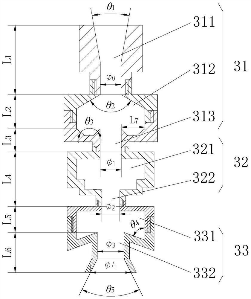
[0053] Among them, the inlet angle of the first water inlet section of the first-stage high-pressure nozzle is θ 1 is 60°, the angle θ of the middle connecting segment 2 is 100°, the angle θ of the ω-shaped structure at ...


PUM

PropertyMeasurementUnit
lengthaaaaaaaaaa
widthaaaaaaaaaa
thicknessaaaaaaaaaa

Abstract

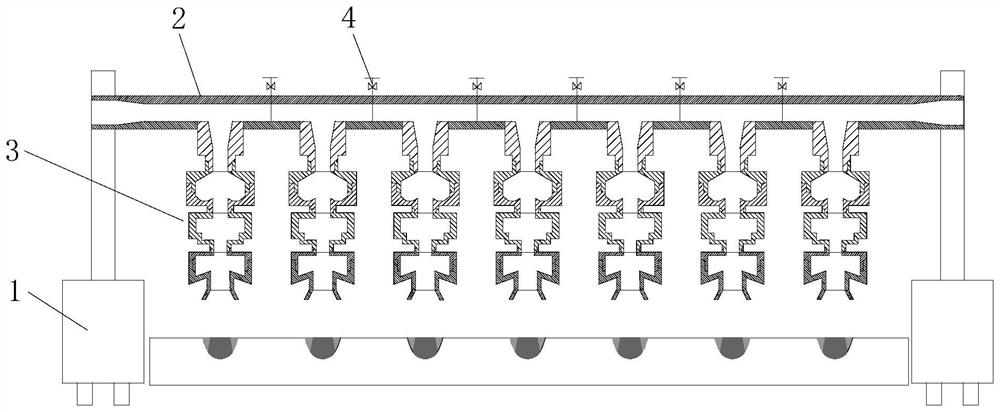
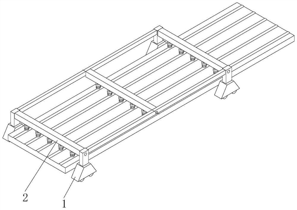
The invention discloses a non-submerged cavitation water jet device capable of efficiently eliminating welding residual stress, which comprises a moving trolley and at least one high-pressure water jet main channel mounted on the moving trolley, the bottom of each high-pressure water jet main channel is detachably connected with at least one multi-cavity cavitation high-pressure nozzle in the length direction of the high-pressure water jet main channel. The multi-cavity cavitation high-pressure nozzle comprises a first-stage high-pressure nozzle body, a second-stage high-pressure nozzle body and a third-stage high-pressure nozzle body which are sequentially connected from top to bottom, the first-stage high-pressure nozzle body, the second-stage high-pressure nozzle body and the third-stage high-pressure nozzle body are coaxially arranged, and the upper end of the first-stage high-pressure nozzle body is connected with the high-pressure water jet main channel. The lower end of the first-stage high-pressure nozzle is connected with the upper end of the second-stage high-pressure nozzle, and the lower end of the second-stage high-pressure nozzle is connected with the upper end of the third-stage high-pressure nozzle. According to the cavitation water jet device, a large number of cavitation bubbles can be formed in the nozzle through the multi-cavity cavitation high-pressure nozzle, and the cavitation jet impact pressure is improved.

Description

technical field [0001] The invention relates to the technical field of cavitation water jet treatment, in particular to a non-submerged cavitation water jet device and method for eliminating welding residual stress with high efficiency. Background technique [0002] At present, the research on cavitation jet technology is increasing day by day. As a new type of water jet, it has the advantages of low working pressure, strong jet impact pressure, environmental protection and energy saving. In recent years, cavitation water jet has been gradually applied to welded structures by domestic and foreign researchers to reduce welding residual stress and improve stress corrosion cracking resistance. However, most of the current cavitation jet devices can only process a single weld, and it is difficult to process multiple welds at the same time. The processing efficiency is low and time consuming is long, which greatly increases the cost of strengthening and water consumption, and ada...

Claims


Application Information

Patent Timeline
Patent Type & Authority Applications(China)
IPC IPC(8): C21D7/06C22F1/00
CPCC21D7/06C22F1/00
Inventor 郑红祥蒋文春胡齐贤罗云王若凡张俏赵治昂康晨阳臧靖宇
Owner CHINA UNIV OF PETROLEUM (EAST CHINA)
Learn More