Anti-dripping coating device for building decoration
An anti-dripping and coating technology, applied in the direction of architecture, building construction, separation methods, etc., can solve the problems of waste, paint dripping, etc., and achieve the effect of avoiding waste
- Summary
- Abstract
- Description
- Claims
- Application Information
AI Technical Summary
Problems solved by technology
Method used
Image
Examples
Embodiment 1
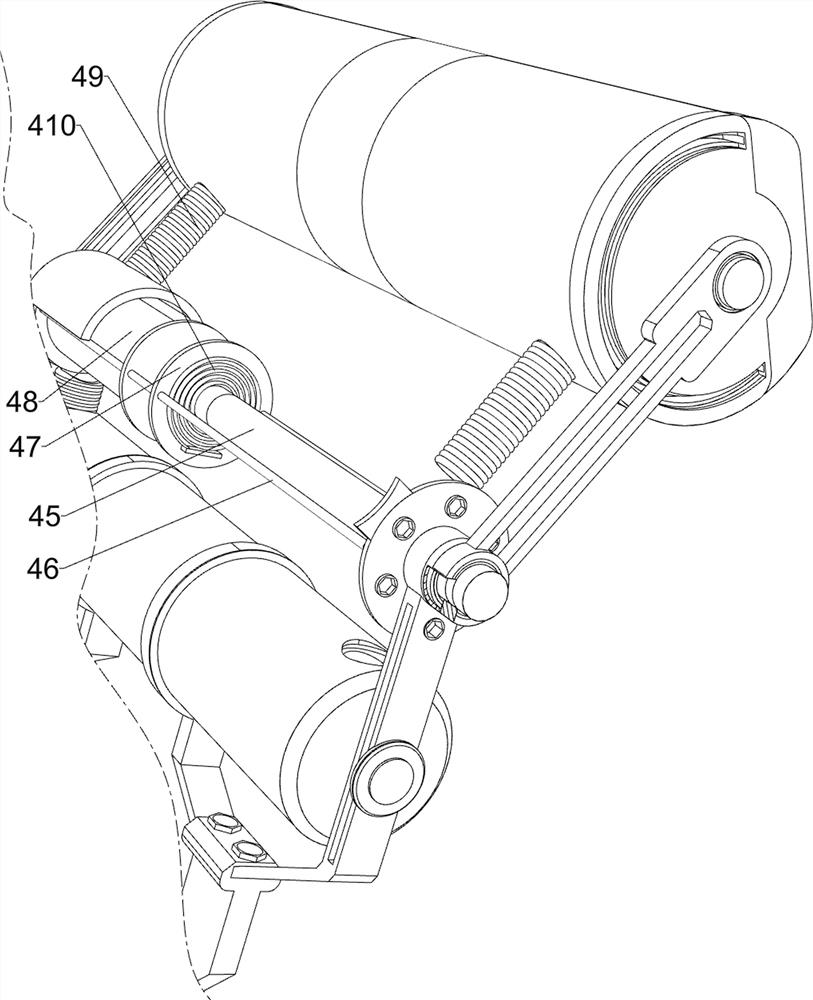
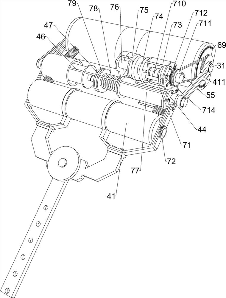
[0039] An anti-drip coating device for building and decoration, comprising a long rod 1, a connecting frame 2, a connecting plate 21, a brushing cylinder 3, an installation shaft 31, a feeding mechanism 4 and an anti-drip mechanism 5, please refer to Figure 1-Figure 8 As shown, a connecting frame 2 is installed on the top of the long rod 1 by welding, and connecting plates 21 are fixed at both ends of the top of the connecting frame 2. A feeding mechanism 4 is installed between the left and right connecting plates 21. When the mechanism 4 is in operation, the feeding mechanism 4 can realize the spraying of paint, and the anti-drip mechanism 5 is installed on the feeding mechanism 4. An installation shaft 31 is rotatably installed between the feeding mechanisms 4, and the brush material cylinder 3 is installed in the middle of the installation shaft 31 by welding in the circumferential direction. When the brush material cylinder 3 rotates, the brush material cylinder 3 can real...
Embodiment 2
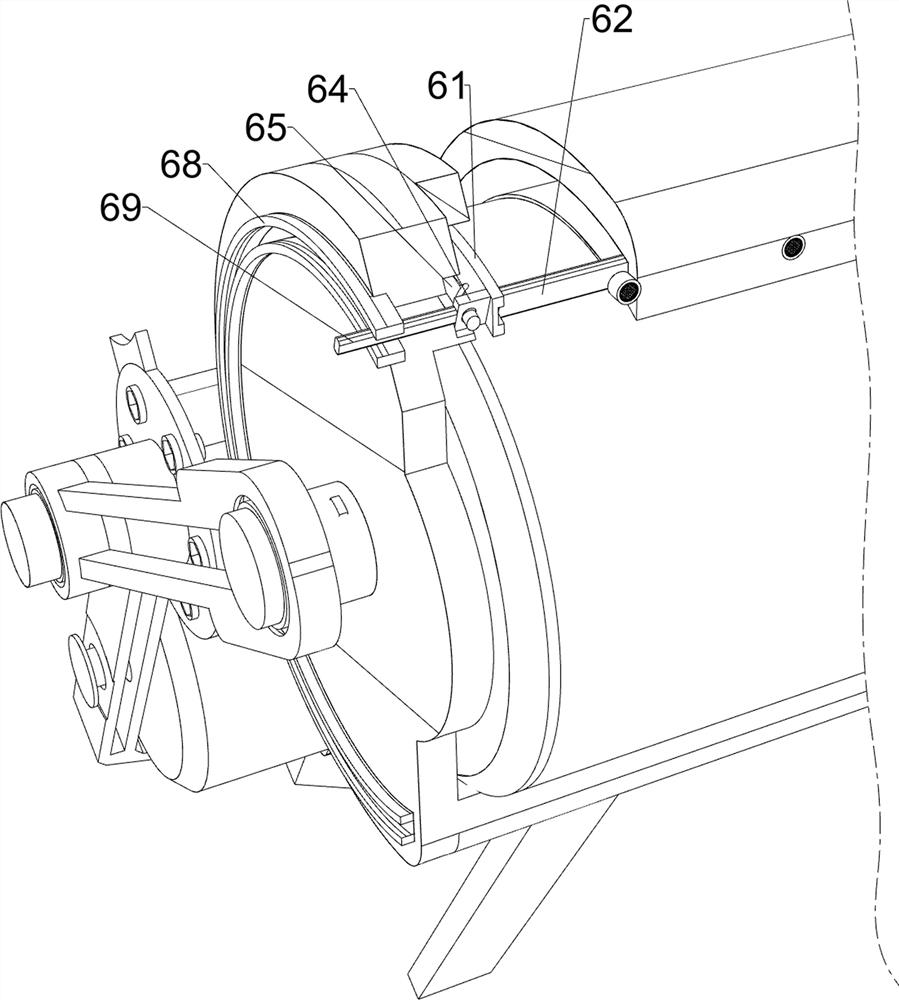
[0046] On the basis of Embodiment 1, it also includes a prompting mechanism 6, and the prompting mechanism 6 includes a partition plate 61, a long plate 62, a first magnet 63, a second magnet 64, an arc-shaped rod 65, an arc-shaped spring 66, a block Plate 67, Rails 68 and Magnets 69, see figure 1 , Figure 9 , Figure 10 , Figure 11 and Figure 12 As shown, in the cavity of the protective shell 52, the partition plates 61 are installed symmetrically by welding, and the inner sides of the partition plates 61 on the left and right sides are slidably connected with the first magnets 63, and the first magnets 63 on the left and right sides. A long plate 62 is fixedly connected between the inner ends, and the long plate 62 is located in the cavity of the protective shell 52 . The outer left and right sides of the protective shell 52 are embedded and fixedly connected with a guide rail 68 , and a magnetic block is slidably connected in the guide rail 68 . 69. The outer end of ...
Embodiment 3
[0051] On the basis of Embodiment 1 and Embodiment 2, a telescopic mechanism 8 is also included. The telescopic mechanism 8 includes a hollow rod 81, a convex block 82 and a second spring 83. Please refer to figure 1 , figure 2 , Figure 14 and Figure 15 As shown, a hollow rod 81 is slidably sleeved on the long rod 1, and six lugs 82 are embedded slidingly connected to the evenly spaced front side of the long rod 1, and the two lugs 82 from the bottom are in contact with the inner side of the hollow rod 81. , the convex block 82 can limit the position of the hollow rod 81 , and a second spring 83 is installed between the rear side of the convex block 82 and the inner side of the long rod 1 by welding.
[0052] Also includes a filter mechanism 9, the filter mechanism 9 includes a fixing ring 91 and a filter screen 92, please refer to figure 2 , image 3 , Figure 16 and Figure 17 As shown, a fixing ring 91 is installed in the hole of the protective shell 52 by welding...
PUM
 Abstract
Description
Claims
Application Information
 - R&D
- Intellectual Property
- Life Sciences
- Materials
- Tech Scout
- Unparalleled Data Quality
- Higher Quality Content
- 60% Fewer Hallucinations
Browse by: Latest US Patents, China's latest patents, Technical Efficacy Thesaurus, Application Domain, Technology Topic, Popular Technical Reports.
© 2025 PatSnap. All rights reserved.Legal|Privacy policy|Modern Slavery Act Transparency Statement|Sitemap|About US| Contact US: help@patsnap.com


