BIM house building system
A technology for houses and components, which is applied in construction, building structure, and processing of building materials, etc., can solve problems such as affecting the normal construction of houses, the driving device does not have the function of dust collection, and the driving device is easy to get stuck and drive normally.
- Summary
- Abstract
- Description
- Claims
- Application Information
AI Technical Summary
Problems solved by technology
Method used
Image
Examples
Embodiment 1
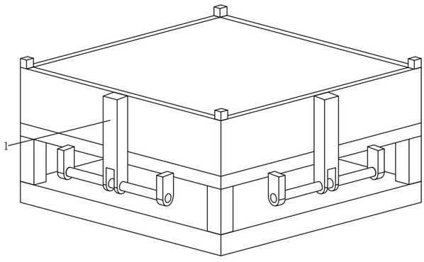
[0055] see Figure 1-6 , in the embodiment of the present invention, a BIM house construction system, including
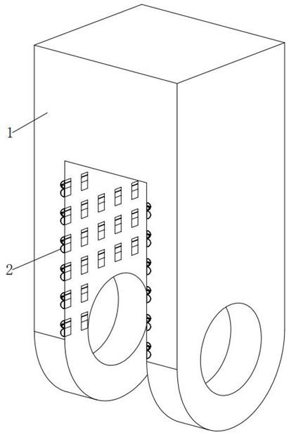
[0056] The fixed plate 1, the inner wall of the bottom longitudinal side of the fixed plate 1 is embedded with a plurality of dust collection components 2 that can collect dust in an up-down and vertical direction in equal adjacent rows;
[0057] The fixing plate 1 here belongs to the driving device of the system, and is fixedly installed outside the side plate of the system;
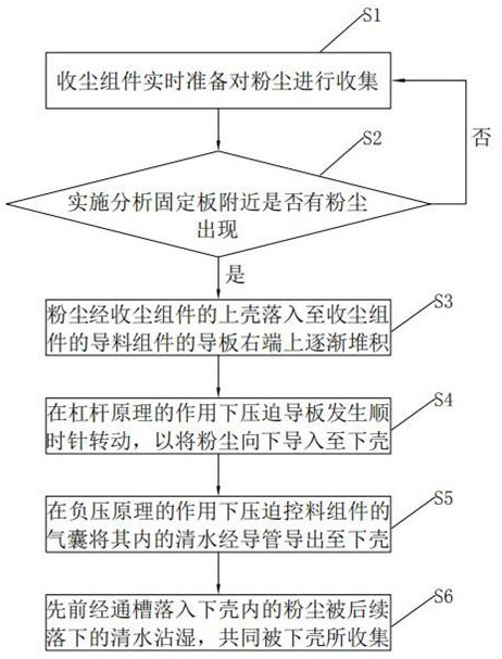
[0058] Dust collecting assembly 2, the dust collecting assembly 2 includes an upper shell 201, a lower shell 202, a material guide assembly 203 that can guide the flow of dust and dust-absorbing materials, and a material control assembly 204 that can control the in and out of the dust-absorbing materials;
[0059] The upper shell 201 is embedded in the inner wall of the bottom end longitudinal side of the fixed plate 1 in an equidistant row in the vertical direction, the inner middle end of...
Embodiment 2
[0067] see image 3 , the difference between the embodiment of the present invention and the embodiment 1 is that the material guide assembly 203 includes:
[0068] The rotating shaft 203a, the inner central position of the upper casing 201 is rotatably installed in the front-rear horizontal direction;
[0069] Guide plate 203b, a guide plate 203b is fixed around the outer surface of the rotating shaft 203a. The guide plate 203b is in a horizontal static equilibrium state under normal conditions. The material of the guide plate 203b is iron. The left and right outer surfaces of the upper shell 201 are respectively fitted with the middle end surfaces of the left and right inner walls of the upper shell 201 under normal conditions;
[0070] The guide plate 203b and the rotating shaft 203a here can facilitate the clockwise rotation of the right end of the guide plate 203b after the accumulation of dust, the rear of the right end of the guide plate 203b and the right inner wall o...
Embodiment 3
[0073] see image 3 , Figure 7-9 , the difference between the embodiment of the present invention and the embodiment 1 is that the material control component 204 includes:
[0074] Limiting plate 204a, the position of the lower end of the left inner wall of the upper shell 201 is vertically up and down. The limiting plate 204a is fixedly installed. The appearance of the limiting plate 204a is in the shape of a number “7” with an inner angle of 90° on a longitudinal section. The bottom end of 204a is fixedly installed at the lower end of the left inner wall of the upper shell 201, the top left end of the limit plate 204s is fixedly installed at the lower end of the left inner wall of the upper shell 201, and the outer surface of the bottom left end of the guide plate 203b is in the normal position. It is placed on the outer surface of the top side of the limit plate 204a under the circumstances, the thickness of the limit plate 204a is less than the thickness of the guide pla...
PUM
 Abstract
Description
Claims
Application Information
 - R&D
- Intellectual Property
- Life Sciences
- Materials
- Tech Scout
- Unparalleled Data Quality
- Higher Quality Content
- 60% Fewer Hallucinations
Browse by: Latest US Patents, China's latest patents, Technical Efficacy Thesaurus, Application Domain, Technology Topic, Popular Technical Reports.
© 2025 PatSnap. All rights reserved.Legal|Privacy policy|Modern Slavery Act Transparency Statement|Sitemap|About US| Contact US: help@patsnap.com


