Heat pump air conditioning system and control method thereof

A heat pump air conditioner and control method technology, which is applied to air conditioner systems, heating methods, refrigerators, etc., can solve the problems of rising refrigerant temperature, limited cooling effect, and reducing the working performance of the air conditioning system, and avoid frost or freezing. , the effect of prolonging the defrosting cycle

Inactive Publication Date: 2022-07-22
ZHUHAI GREE REFRIGERATION TECH CENT OF ENERGY SAVING & ENVIRONMENTAL PROTECTION
View PDF6 Cites 1 Cited by
  • Summary
  • Abstract
  • Description
  • Claims
  • Application Information

AI Technical Summary

Problems solved by technology

[0004] The applicant of this application applied for the patent 202010159387.0 in the early stage, which adopts the structural form of the main heat exchanger and the defrosting heat exchanger. The two are connected in series and a throttling device is connected between them to delay the frosting of the main heat exchanger. However, due to the temperature rise of the refrigerant after evaporating and absorbing heat in the main heat exchanger, its cooling effect may be limited when it passes through the defrosting heat exchanger, which results in limited air dehumidification ability and delays the process of frosting. Not particularly impressive
[0005] However, for this air conditioning system, since the two outdoor heat exchangers are in the state of evaporating and absorbing heat during heating, the frosting frequency of the two outdoor heat exchangers is basically the same. The system needs to enter the defrosting control for a short period of time in the heating condition, which reduces the working energy efficiency of the air conditioning system, shortens the high-energy-efficiency running time of the heating condition, and reduces the working performance of the air conditioning system

Method used


Image

  • Heat pump air conditioning system and control method thereof
  • Heat pump air conditioning system and control method thereof
  • Heat pump air conditioning system and control method thereof

Examples


no. 1 example

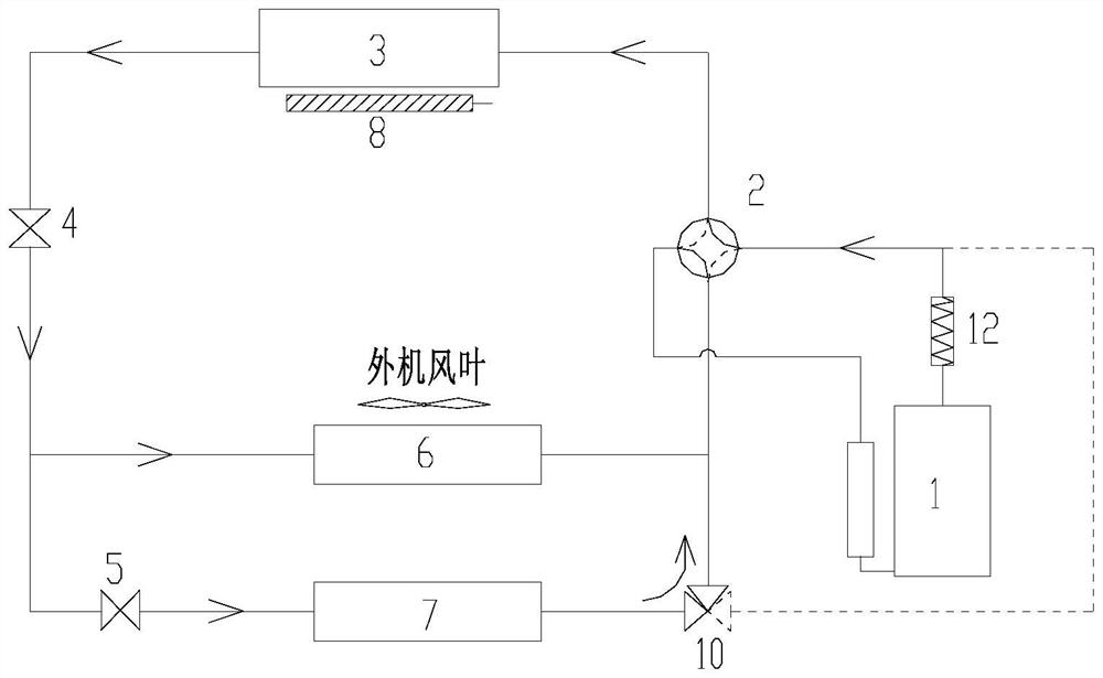
[0062] The first embodiment: the system cycle of the heat pump air conditioner of the present invention during heating is as follows figure 1 As shown in the figure, the refrigerant heating device is installed on the compressor discharge port pipeline. After the refrigerant comes out of the compressor discharge port, it passes through the refrigerant heating device, then enters the internal heat exchanger, and then enters the first section after passing through the internal heat exchanger. Flow device 4, a part of the throttled low-temperature and low-pressure refrigerant enters the external machine heat exchanger 1 (main heat exchanger 6) to exchange heat with the outside air, and the other part of the refrigerant passes through the second throttling device 6, and the refrigerant passes through the secondary throttling. Then it enters the second external heat exchanger (defrosting heat exchanger 7) to exchange heat with the outside air. The refrigerant from the external heat e...

no. 2 example

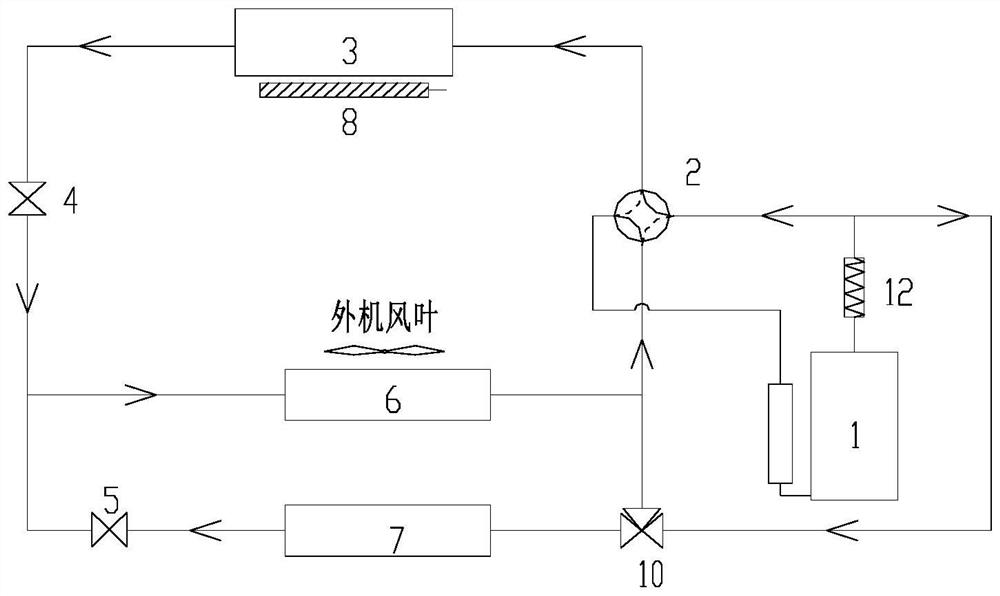
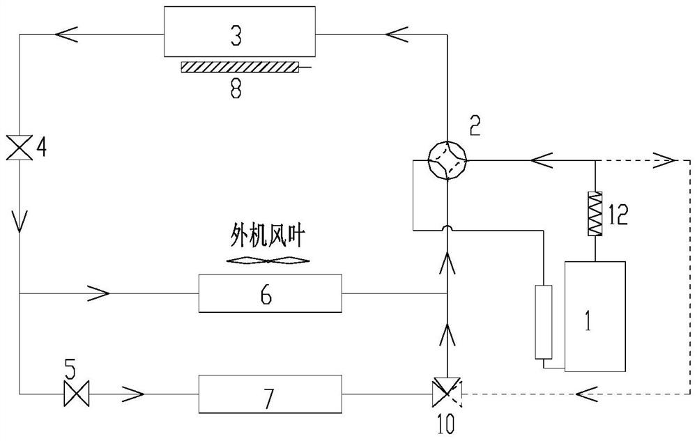
[0082] Second embodiment: The second embodiment of the present invention is to set the refrigerant heating device of the first embodiment on the circuit of the suction port of the compressor. In low temperature conditions, when the heat pump air conditioner is in heating operation, the refrigerant heating device is turned on by controlling the system to increase the suction temperature and exhaust temperature of the compressor, so as to inhibit frost formation and prolong the heating time. Thermal system cycles such as Figure 5 shown. During the defrosting period, when the heat pump air conditioner is running, turn on the refrigerant heating device to increase the suction temperature and exhaust temperature of the compressor, and the high temperature gas can speed up the defrosting speed of the outdoor unit. like Figures 6 to 8 shown.

no. 3 example

[0083] Third embodiment: The third embodiment of the present invention is to set the refrigerant heating device of the first embodiment on the pipeline between the second external heat exchanger (ie, the defrosting heat exchanger 7 ) and the three-way valve. In low temperature conditions, when the heat pump air conditioner is in heating operation, through the control of the system, the refrigerant heating device is turned on to increase the suction temperature and exhaust temperature of the compressor, so as to inhibit frost formation and prolong the heating time. loop like Figure 9 shown. When the heat pump air conditioner is running during defrosting, the refrigerant from the compressor is heated by the refrigerant heating device and then passes through the outdoor heat exchanger 2. The high-temperature gas can speed up the defrosting speed of the outdoor unit, ensure the indoor comfort during defrosting, and improve the heat pump. performance, the system cycle during defr...


PUM


Abstract

The invention provides a heat pump air conditioning system and a control method thereof. The system comprises a compressor, a four-way valve, an indoor heat exchanger, a first throttling device, a second throttling device, a main heat exchanger and a defrosting heat exchanger, the defrosting heat exchanger is located on the air flowing upstream side of the main heat exchanger, and the second throttling device and the defrosting heat exchanger are connected in series to form a defrosting pipeline. A refrigerant is divided into two paths after passing through the indoor heat exchanger and the first throttling device from an exhaust port of the compressor, one path flows back to the compressor through the main heat exchanger, and the other path enters the defrosting heat exchanger after being throttled through the second throttling device and then flows back to the compressor. And a refrigerant heating device is arranged on at least one of the exhaust pipeline, the air suction pipeline and the defrosting pipeline of the compressor. According to the heat pump air conditioning system, the frosting frequency of the main outdoor heat exchanger can be further reduced, the heat input of a refrigerant of the whole system can be enhanced, the heating duration is prolonged, and continuous indoor heat supply is achieved in the defrosting period.

Description

technical field [0001] The present application relates to the technical field of air conditioning, in particular to a heat pump air conditioning system and a control method thereof. Background technique [0002] When the heat pump air conditioner is used under low temperature conditions, after running for a period of time, the external heat exchanger will be frosted, which increases the thermal resistance and wind resistance, which is not conducive to heat exchange and makes the performance of the air conditioner worse. In order to make the air conditioner operate normally, The air conditioner needs to be defrosted. The main defrosting method of the existing air conditioner is to switch the four-way valve to reverse the direction of the four-way valve. In this way, during the defrosting process, the indoor fan is stopped, which not only cannot provide heat to the room, but also The cooler has a lower refrigerant temperature and also absorbs heat from the room, lowering the ...

Claims


Application Information

Patent Timeline
Patent Type & Authority Applications(China)
IPC IPC(8): F24F1/16F24F13/30F24F11/42F24F11/70F25B5/02F25B6/02F25B13/00F25B41/20F25B47/02F25B49/02
CPCF24F1/16F24F13/30F24F11/42F24F11/70F25B5/02F25B6/02F25B13/00F25B41/20F25B47/02F25B47/022F25B47/025F25B49/02
Inventor 李丽芳彭光前车雯王喜成王现林杨伟王锐锋孙伟佳叶培龙高仲灶于琦梁凯文
Owner ZHUHAI GREE REFRIGERATION TECH CENT OF ENERGY SAVING & ENVIRONMENTAL PROTECTION
Why Eureka
Try Eureka