Double-break isolating switch

A isolating switch and double-break technology, which is applied in the field of double-break isolating switches, can solve the problems of high production cost of parts, slow opening and closing response speed, etc., and achieve the effect of large moving distance, improved response speed, and guaranteed opening distance

Pending Publication Date: 2022-07-22
PINGGAO GRP +3
View PDF1 Cites 0 Cited by
  • Summary
  • Abstract
  • Description
  • Claims
  • Application Information

AI Technical Summary

Problems solved by technology

[0007] The purpose of the present invention is to provide a double-break isolating switch to solve the problems of slow opening and closing response speed and relatively high cost of parts in the current double-break isolating switch

Method used


Image

  • Double-break isolating switch
  • Double-break isolating switch
  • Double-break isolating switch

Examples


Embodiment 1

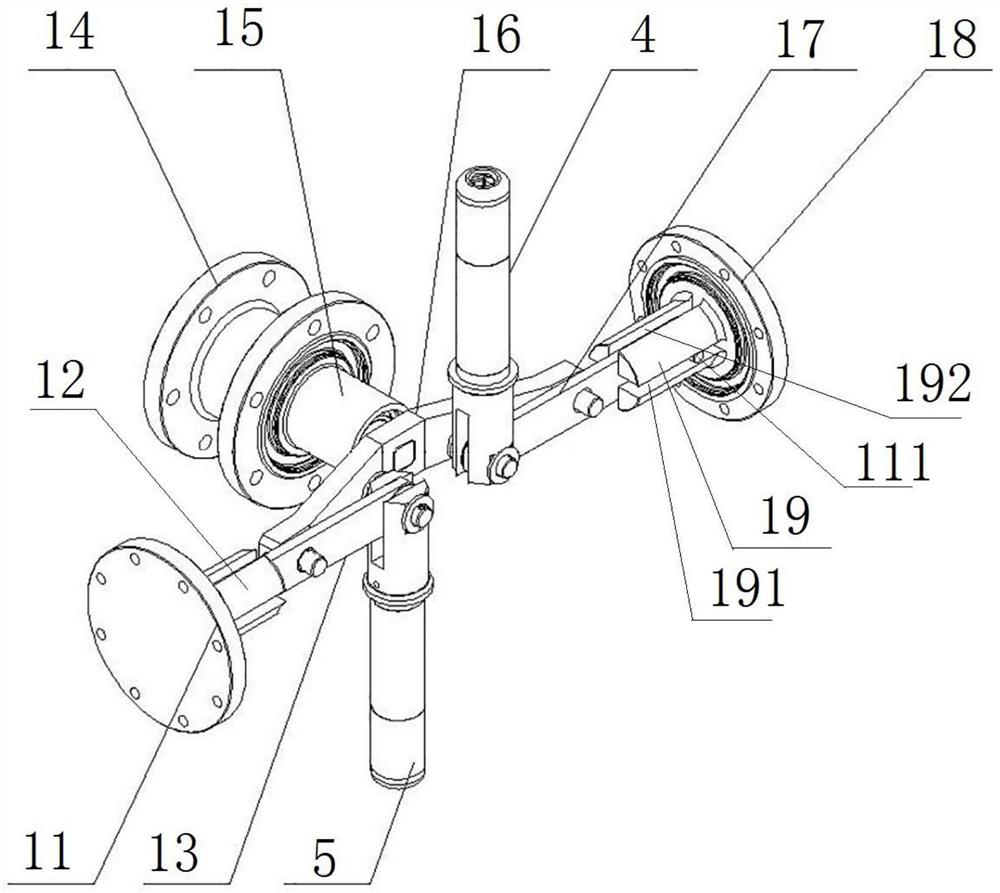
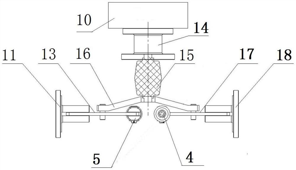
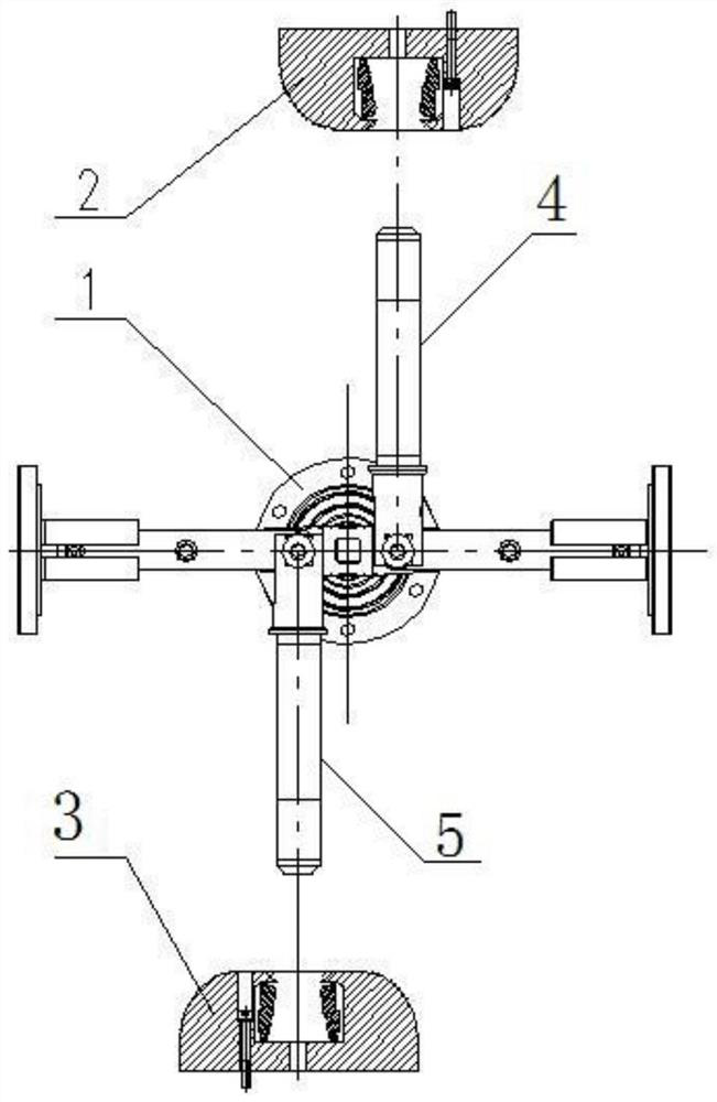
[0044] The double-break isolating switch includes a casing, the inner cavity of the casing forms a sealed air chamber, two supporting insulators arranged oppositely are arranged on the casing, and a static contact seat is arranged on the supporting insulator, and the static contact seats on the two supporting insulators respectively constitute the first static contact seat. The contact seat and the second static contact seat, the first static contact seat is provided with a first static contact 2, the second static contact seat is provided with a second static contact 3, the first static contact 2 and the second static contact The heads 3 are arranged in a staggered manner, and the oppositely arranged first stationary contacts 2 are parallel to the central axes of the second stationary contacts 3; the housing is also provided with a movable contact seat (not shown in the figure), and the movable contact seat passes through the insulating support Fixed in the air chamber, the mo...

Embodiment 2

[0057] The difference between this embodiment and Embodiment 1 is that the guiding moving paths of the first moving contact and the second moving contact in Embodiment 1 are parallel to each other and spaced in a direction perpendicular to the moving paths. In this embodiment, as Image 6 and Figure 7 As shown in the figure, the guiding movement paths of the first movable contact 04 and the second movable contact 03 are collinear, and correspondingly, the first stationary contact and the second stationary contact are on the same axis, so that the entire movable end can be assembled on the same axis. Whether it is perpendicular to the direction of the moving contact guide movement or which structure is more compact is suitable for different use requirements.

Embodiment 3

[0059] The difference between this embodiment and Embodiment 1 is that the main arm in Embodiment 1 is arched. In this embodiment, the main arm is U-shaped, and the two opposite arms of the U-shape are used for hinged connection with the two connecting rods, or in other embodiments, the main arm is a straight plate structure, and the movable contact is hinged on the connection. side of the rod.


PUM


Abstract

The invention relates to a double-break disconnecting switch which comprises a shell, a first static contact seat and a second static contact seat are relatively fixed in the shell, a movable contact seat is arranged between the first static contact seat and the second static contact seat, a first movable contact and a second movable contact are assembled on the movable contact seat in a guiding and sliding mode, and a driving structure comprises a transmission shaft and an operating mechanism. The transmission shaft drives the first moving contact and the second moving contact to synchronously act through a transmission structure in the shell to achieve opening and closing, the transmission structure in the shell comprises a main crank arm, the transmission shaft is connected to the middle of the main crank arm in a rotation stopping mode, the two ends of the main crank arm are in linkage with two transmission assemblies respectively, and each transmission assembly comprises a connecting rod. One end of the connecting rod is hinged to the moving contact, a guide structure used for guiding the other end of the connecting rod is arranged in the shell, the guide direction of the guide structure is perpendicular to the guide moving direction of the moving contact, the moving requirement of the moving contact can be met when the main crank arm rotates less than one circle, and the response speed of opening and closing can be improved.

Description

technical field [0001] The invention belongs to the field of high-voltage AC and DC power transmission and transformation, and in particular relates to a double-break isolating switch suitable for uninterrupted expansion, maintenance and testing of bus bars. Background technique [0002] With the development of economy and society and the improvement of people's living standards, the whole society has higher and higher requirements for the reliability of power supply, and has a lower and lower tolerance for power outages. It's getting harder to plan outages. However, in order to reduce the cost of infrastructure and operation and maintenance, larger GIS power stations are generally constructed in stages, and most of the GIS power stations need to be expanded. However, only the expansion interface is reserved for the equipment part of the first phase of GIS products. When a certain interval fails, the interval needs to be repaired separately, and the busbar power failure is ...

Claims


Application Information

Patent Timeline
Patent Type & Authority Applications(China)
IPC IPC(8): H01H31/02H01H3/46H01H3/32H01H3/50
CPCH01H31/02H01H3/46H01H3/32H01H3/50
Inventor 柴影辉魏建巍占小猛谭盛武段晓辉杨敏董祥渊贺永明谢世超高远温铭丽徐华靳幸福李斐鲁世浩井琼琼庞建张振苏士伟
Owner PINGGAO GRP
Why Eureka
Try Eureka