Automatically-controlled multi-angle waist movable chair
A multi-angle, waist technology, used in passive exercise equipment, massage aids, physical therapy and other directions, can solve problems such as unsatisfactory, untargeted, unable to support legs well, and achieve reasonable structural design and lightening. Social burden, structurally sound effects
- Summary
- Abstract
- Description
- Claims
- Application Information
AI Technical Summary
Problems solved by technology
Method used
Image
Examples
Embodiment 1
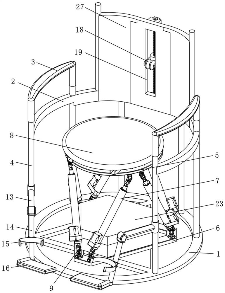
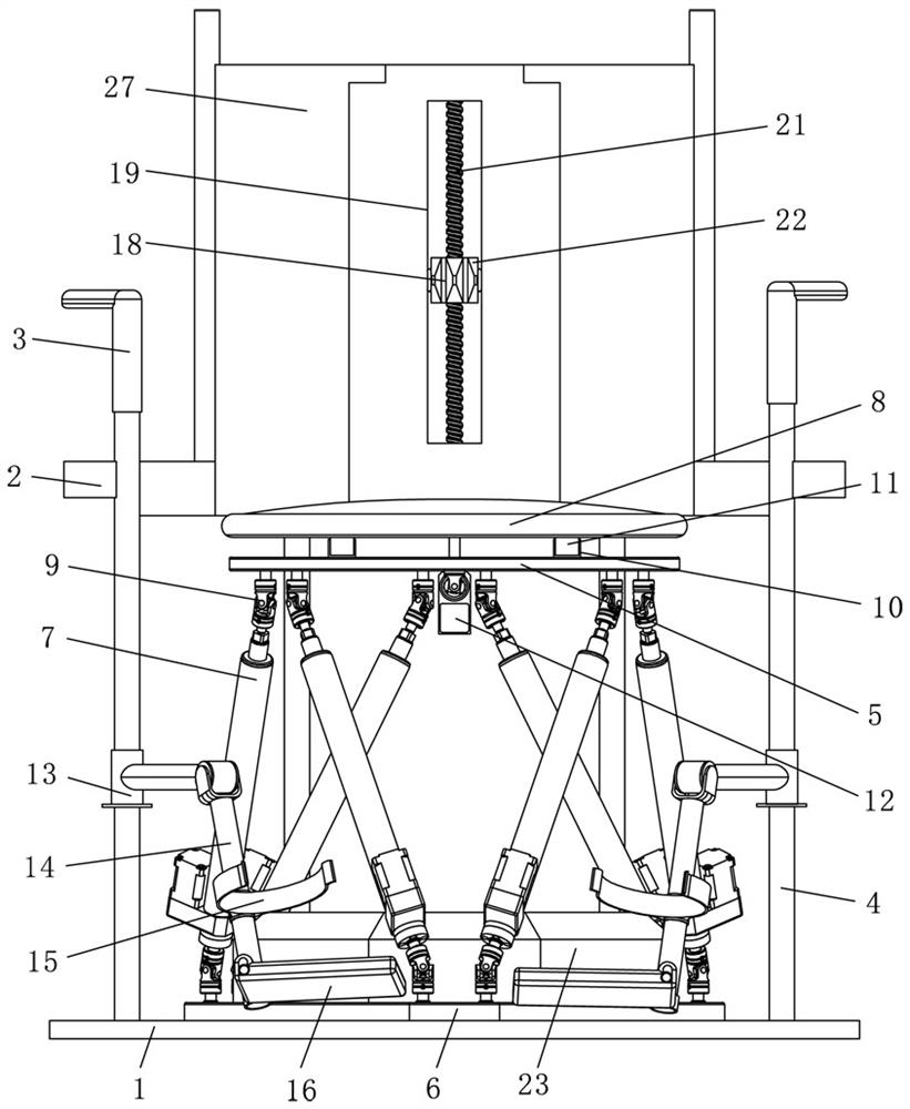
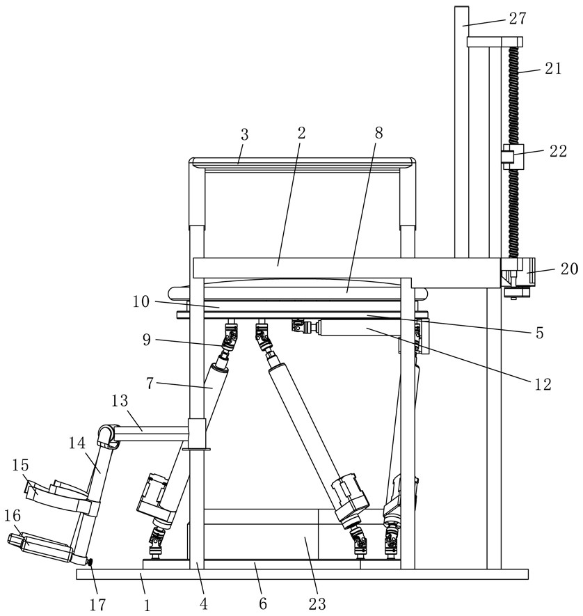
[0032] like Figure 1~Figure 5 As shown, an automatically controlled multi-angle lumbar movable chair includes a movable seat, and the movable seat includes a seat frame, a multi-degree-of-freedom seat platform arranged in the middle of the seat frame, and two front and rear seats of the seat frame. The end of the leg support mechanism and the back plate 27 and the back massage mechanism provided on the back plate 27.
[0033] As the main body of the movable seat, the seat frame includes a circular hollow bottom plate 1, a curved top plate 2, an armrest 3 and a vertical rod 4. The top plate 2 and the bottom plate 1 are arranged at intervals up and down, and the top plate 2 is along the The edge of the bottom plate 1 is bent in an arc shape, the armrests 3 are arranged on both sides of the top plate 2, and a plurality of the vertical rods 4 are arranged between the top plate 2 and the bottom plate 1 for connection, thereby forming a seat frame structure.
[0034] In this embod...
Embodiment 2
[0055] like Image 6 As shown in the figure, this embodiment is basically the same as the first embodiment, and the similarities will not be repeated. 24 is sleeved on the vertical rods 4 at both ends of the seat frame, and the compression springs 24 abut between the bottom of the seat frame and the end of the strut-13, which can support the leg support mechanism.
[0056] Both sides of the front end of the seat frame are also provided with latches 25 to restrain the compression spring 24 . After the compression spring 24 is passively compressed, the plug 25 is inserted into the vertical rod 4. At this time, the compression spring 24 can be restricted by the plug 25 to make it in a compressed state. At this time, the upward movement of the leg support mechanism is passively driven by the leg of the person. .
[0057] Once the latch 25 is pulled out, the compression spring 24 stretches against the strut one 13, so that the leg support mechanism can elastically slide up and do...
Embodiment 3
[0059] like Figure 7 As shown, this embodiment is basically the same as the first embodiment, and the similarities will not be repeated. The difference is that sliding holes 19 are also vertically opened on both sides of the back plate 27, and the sliding holes 19 on both sides are used for Accommodates massage rollers 18 . Specifically, brackets 26 are respectively provided in the sliding holes 19 on both sides. The brackets 26 are “F”-shaped in cross section. One end is connected to the lead screw nut 22 .
[0060] In this embodiment, the number of the massage wheels 18 is three, the three massage wheels 18 are evenly distributed on the back plate 27, the lead screw nut 22 moves up and down, and the bracket 26 can drive the other two massage wheels 18 to move up and down, The synchronous movement of the three massage wheels 18 can massage the back of the person in all directions, which can effectively improve the massage effect.
PUM
 Abstract
Description
Claims
Application Information
 - R&D
- Intellectual Property
- Life Sciences
- Materials
- Tech Scout
- Unparalleled Data Quality
- Higher Quality Content
- 60% Fewer Hallucinations
Browse by: Latest US Patents, China's latest patents, Technical Efficacy Thesaurus, Application Domain, Technology Topic, Popular Technical Reports.
© 2025 PatSnap. All rights reserved.Legal|Privacy policy|Modern Slavery Act Transparency Statement|Sitemap|About US| Contact US: help@patsnap.com


