Forming method of sheet metal component with composite characteristics of bulge rib and groove
What is AI technical title?
AI technical title is built by Patsnap AI team. It summarizes the technical point description of the patent document.
A compound feature and bulging technology, applied in the field of sheet metal forming processing, can solve problems such as poor forming quality, achieve high pass rate, improve overall forming quality, and facilitate control
Active Publication Date: 2022-07-29
CHENGDU AIRCRAFT INDUSTRY GROUP
View PDF11 Cites 0 Cited by
Summary
Abstract
Description
Claims
Application Information
AI Technical Summary
This helps you quickly interpret patents by identifying the three key elements:
Problems solved by technology
Method used
Benefits of technology
Problems solved by technology
[0004]The main purpose of this application is to provide a forming method for sheet metal components with compound features of rib grooves and bulges, aiming at Technical Problems of Poor Forming Quality in Forming Methods of Gold Parts
Method used
Image
Click on the blue label to locate the original text in one second.
Reading with bidirectional positioning of images and text.
Examples
Embodiment 1
[0056] refer to Figure 1-Figure 13 , this embodiment provides a method for forming a sheet metal component with a composite feature of bulging ribs and grooves, including the following steps:
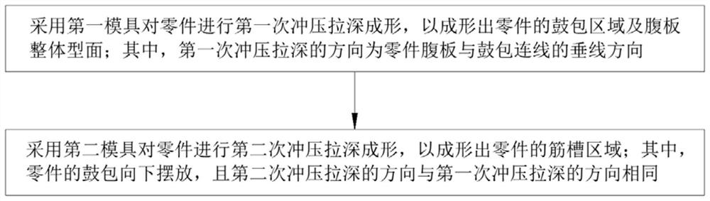
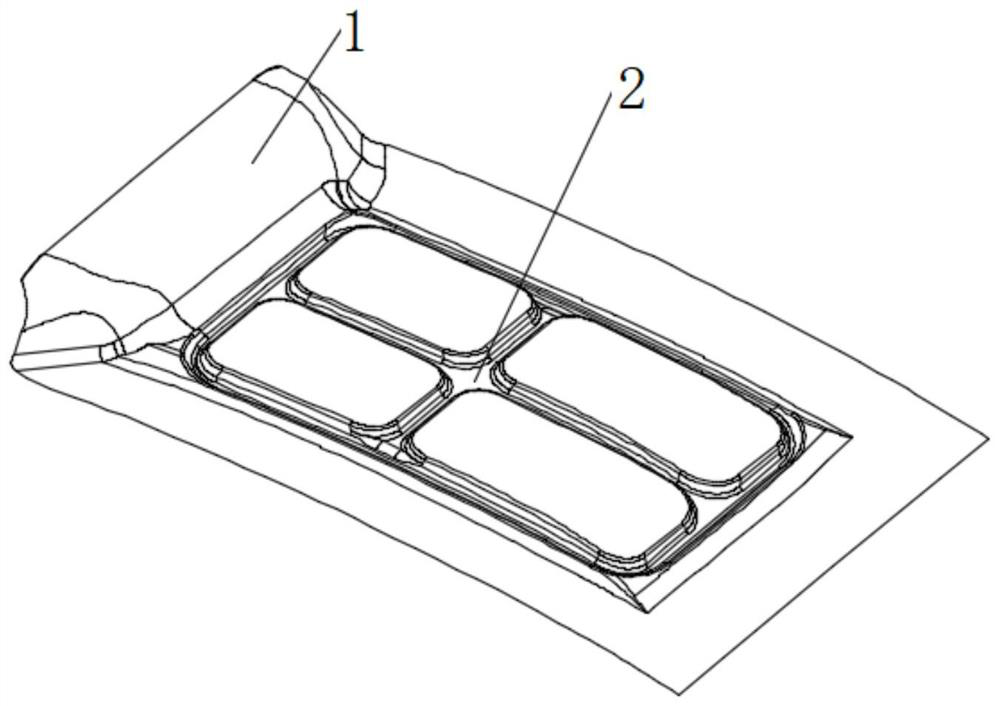
[0057] The first die is used to carry out the first stamping and deep drawing of the part, so as to form the bulge area 1 of the part and the overall profile of the web; wherein, the direction of the first stamping and deep drawing is the vertical line between the part's web and the bulge. line direction;
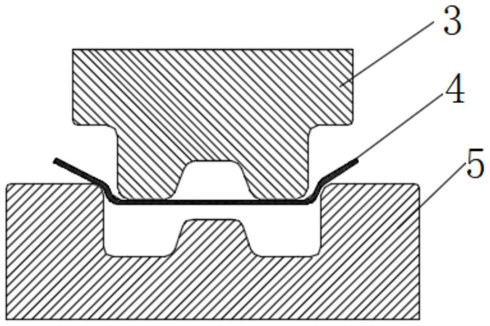
[0058] The second die is used to carry out the second stamping and deep drawing of the part to form the rib groove area 2 of the part; wherein, the bulge of the part is placed downward, and the direction of the second stamping and drawing is the same as that of the first stamping and drawing. The deep direction is the same.
[0059] Since the current forming of complex sheet metal parts for the composite features of such bulging ribs and grooves mainly relies on the drop hammer pr...
Embodiment 2
[0105] refer to Figure 4-Figure 13 , this embodiment provides a method for forming a sheet metal component with a composite feature of bulging ribs and grooves, including the following steps:
[0106] Using two-pass stamping and deep drawing, the bulge area 1 and the web profile of the first forming part are formed with the bulge facing up, and the rib groove area 2 of the second forming part, the bulge area is facing down;
[0107] When designing the mold, the first mold is provided with an exhaust hole 15 in the non-working area of the bulge, and a storage bulge in the web area. Taking 4 cavities as an example, the original size of the cavity is:
[0108] 1) The dimensions of the two cavities near the bulge area 1 are: L 1 =202mm, L 2 =185mm, B 1 =126mm, B 2 =114mm, H=14mm;
[0109] 2) The dimensions of the two cavities away from the bulge area 1 are: L 1 =252mm, L 2 = 237mm, B 1 =134mm, B 2 =118mm, H=14mm;
[0110] The dimensions of the design storage drum are ...
PUM
Abstract
The invention discloses a bulging rib and groove composite characteristic sheet metal component forming method which comprises the following steps that a first die is adopted for conducting first-time stamping and deep drawing forming on a part so as to form a bulging area of the part and a web overall molded surface; wherein the direction of the first-time stamping and drawing is the direction of a vertical line of a connecting line of a part web and a bump; a second die is adopted for conducting secondary stamping and drawing forming on the part so that a rib groove area of the part can be formed; wherein a bulge of the part is placed downwards, the direction of the second time of stamping and drawing is the same as the direction of the first time of stamping and drawing, and the method has the advantages that the forming quality and the process stability of the sheet metal part with the rib groove and bulge composite characteristic are improved, and the formed part is good in performance and long in service life.
Description
technical field [0001] The present application relates to the technical field of sheet metal forming and processing, and in particular, to a method for forming a sheet metal component with a composite feature of bulging ribs and grooves. Background technique [0002] Aviation sheet metal parts can be divided into three categories: pipes, profiles and plates according to the type of raw materials. Among them, sheet metal parts can be divided into half-pipe, plate frame, skin, long truss and other types according to their structural characteristics. , such parts usually cannot be formed by a single process such as conventional rubber bladder hydroforming, skin stretch forming, and liquid-filling forming, and need to be formed by multiple processes or multi-pass processes in combination with the structural characteristics of the parts. [0003] Ribs and bulges are typical features in complex sheet metal parts, and the combination of the two features makes the forming of parts ...
Claims
Application Information
Patent Timeline
Application Date:The date an application was filed.
Publication Date:The date a patent or application was officially published.
First Publication Date:The earliest publication date of a patent with the same application number.
Issue Date:Publication date of the patent grant document.
PCT Entry Date:The Entry date of PCT National Phase.
Estimated Expiry Date:The statutory expiry date of a patent right according to the Patent Law, and it is the longest term of protection that the patent right can achieve without the termination of the patent right due to other reasons(Term extension factor has been taken into account ).
Invalid Date:Actual expiry date is based on effective date or publication date of legal transaction data of invalid patent.

