
Automatic putting and recycling equipment

A recovery equipment and automatic release technology, which is applied in the direction of motor vehicles, rotorcraft, aircraft, etc.

Pending Publication Date: 2022-07-29
STATE GRID JIBEI ELECTRIC POWER COMPANY LIMITED CHENGDE POWER SUPPLY +1
View PDF0 Cites 0 Cited by
  • Summary
  • Abstract
  • Description
  • Claims
  • Application Information

AI Technical Summary

Problems solved by technology

These operations are very dangerous

Method used


Image

  • Automatic putting and recycling equipment
  • Automatic putting and recycling equipment
  • Automatic putting and recycling equipment

Examples


Embodiment Construction

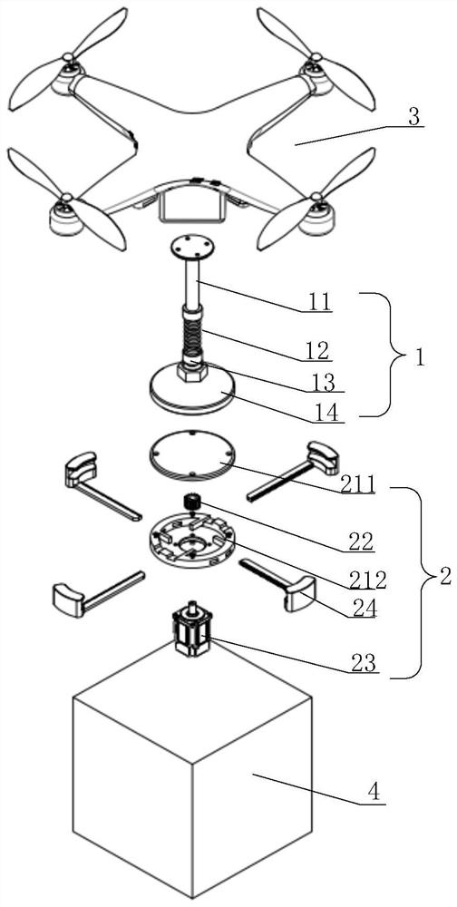
[0026] The invention discloses an automatic throw-in and recovery device, which can realize the automatic throw-in and recovery of operation equipment, thereby reducing the danger of electric operation and reducing labor costs.

[0027] The technical solutions in the embodiments of the present invention will be clearly and completely described below with reference to the accompanying drawings in the embodiments of the present invention. Obviously, the described embodiments are only a part of the embodiments of the present invention, not all of the embodiments. Based on the embodiments of the present invention, all other embodiments obtained by those of ordinary skill in the art without creative work fall within the protection scope of the present invention.

[0028] In the description of the present invention, the orientation or positional relationship indicated by the terms "upper", "lower", etc. is based on the orientation or positional relationship shown in the accompanying ...


PUM


Abstract

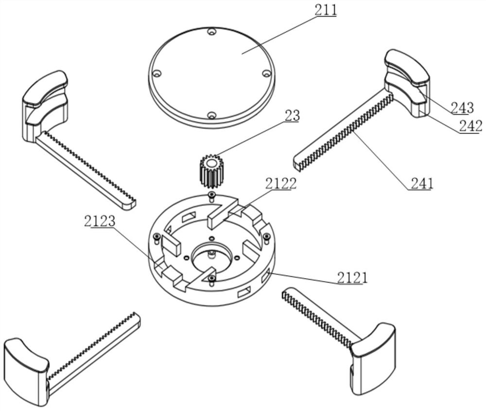
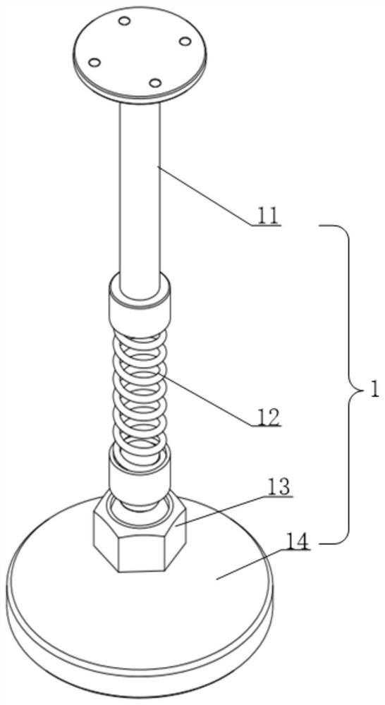
The invention discloses automatic putting and recycling equipment which comprises an unmanned aerial vehicle, an electromagnet assembly and a suction plate assembly. The electromagnet assembly comprises a suspender and an electromagnet, one end of the suspender is connected with the unmanned aerial vehicle, and the other end of the suspender is connected with the electromagnet; the suction plate assembly comprises a suction plate seat and a telescopic lock catch, the suction plate seat is connected to operation equipment, and when the electromagnet is electrified, the electromagnet can be attracted to the suction plate seat; the telescopic lock catch stretches out and draws back in the radial direction of the suction plate base, and the telescopic lock catch can push the electromagnet on the suction plate base when contracting. The number of the telescopic lock catches is multiple, the multiple telescopic lock catches are arranged around the center of the suction plate base, and the multiple telescopic lock catches stretch out and draw back synchronously. According to the automatic putting and recycling equipment, automatic putting and recycling of the operation equipment can be achieved, so that the danger of electric power operation is reduced, and the labor cost is reduced.

Description

technical field [0001] The invention relates to the field of throwing and recycling of operating equipment, and more particularly, to an automatic throwing and recycling device. Background technique [0002] In high-altitude live work on transmission lines, operators often need to carry live work equipment to climb up the tower, or need to carry live work equipment to work on live conductors and ground wires. There is also a need to recover live work equipment from the wire. These operations are very dangerous. SUMMARY OF THE INVENTION [0003] The purpose of the present invention is to realize the automatic throwing and recovery of operating equipment, thereby reducing the danger of electric operation and reducing labor costs. To achieve the above object, the present invention provides the following technical solutions: [0004] An automatic throwing and recycling device includes a drone, an electromagnet assembly and a suction plate assembly; the electromagnet assembl...

Claims


Application Information

Patent Timeline
Patent Type & Authority Applications(China)
IPC IPC(8): B64D1/00B64D1/12B64C27/08
CPCB64D1/00B64D1/12B64C27/08B64U10/10B64U2101/60B64U2201/20
Inventor 鲁杰郭金智张兆广庞博宋新利侯力枫白雪松陈建季宁刘明辉李壮宁岩杨广涛范士清柴振华席海阔
Owner STATE GRID JIBEI ELECTRIC POWER COMPANY LIMITED CHENGDE POWER SUPPLY
Learn More