
One-way safety tongs

A safety gear, one-way technology, applied in the field of safety gear, can solve the problems of large installation space, increased size of safety gear, large friction coefficient, etc., and achieve the effect of small structural space and stable braking

Pending Publication Date: 2022-07-29
HANGZHOU HUNING ELEVATOR PARTS CO LTD
View PDF1 Cites 0 Cited by
  • Summary
  • Abstract
  • Description
  • Claims
  • Application Information

AI Technical Summary

Problems solved by technology

[0002] Existing one-way safety tongs, for example, the single wedge lifting type safety tongs disclosed in the patent document CN202687686U, its fixed brake assembly includes a fixed brake block and a disc spring group, which requires a large installation space, The size of the safety gear increases; in addition, since the fixed brake block cannot move along the extension direction of the elevator guide rail, and there is a large friction coefficient between the fixed brake block and the guide rail, a large reverse force is required to achieve the reset when resetting
At the same time, due to the change of the state of the medium between the friction block and the guide rail or the processing state of the guide rail, there are dual parts that require strict control and can reduce risks only after confirmation through tests

Method used


Image

  • One-way safety tongs
  • One-way safety tongs
  • One-way safety tongs

Examples


Embodiment 1

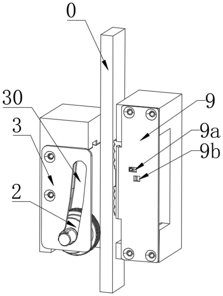
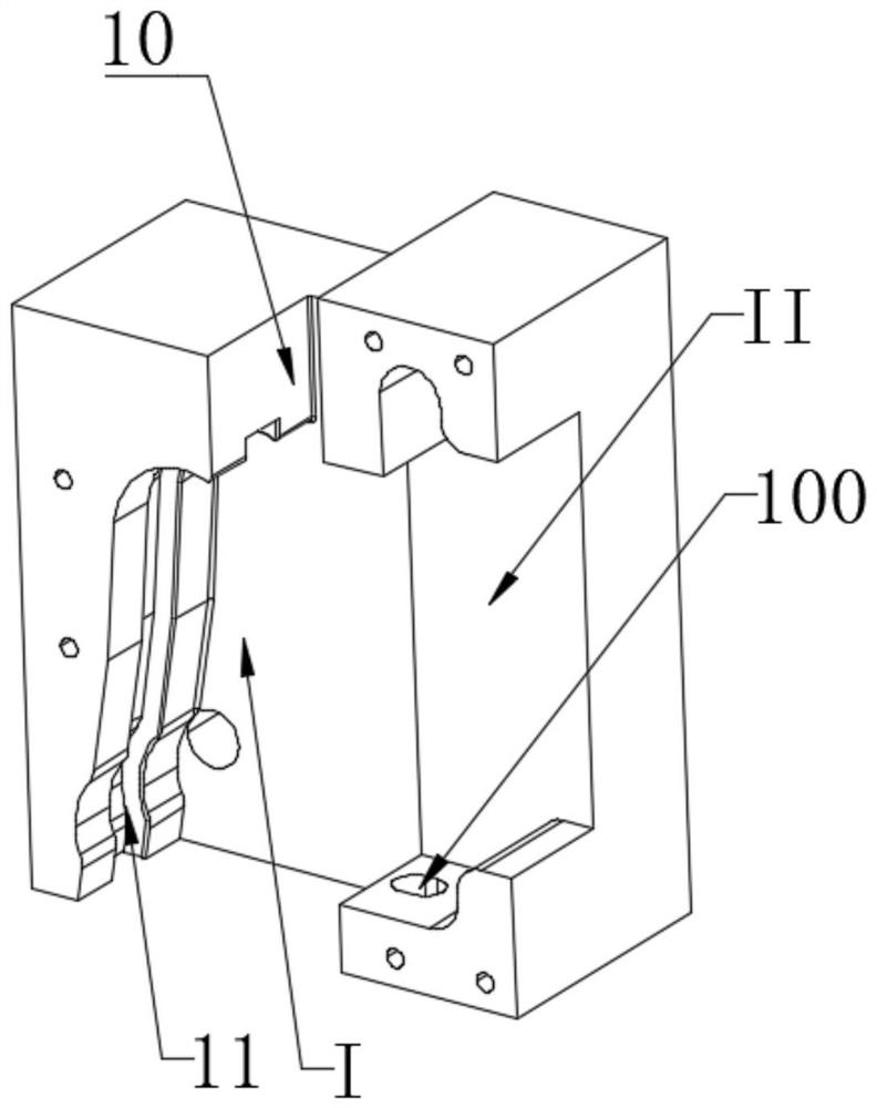
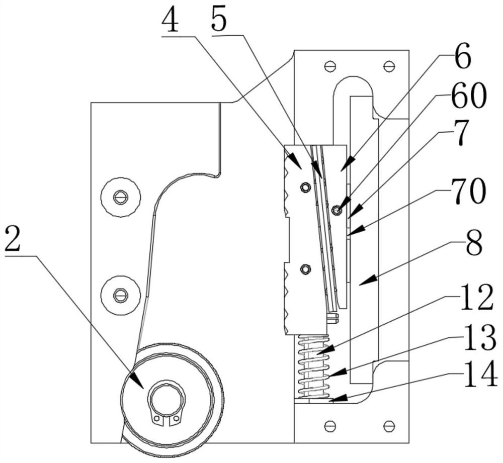
[0025] like Figure 1-4 As shown, the one-way safety gear of this embodiment includes a caliper body 1, a braking roller 2, a guide plate 3, a fixed wedge 4, a ball cage 5, a sliding seat 6, an adjustment pad 7, and a strip spring 8 , cover plate 9.

[0026] Specifically, the caliper body 1 has a vertically extending guide rail channel 10. The caliper body 1 is located on the left and right sides of the guide rail channel 10 to form a first concave portion I and a second concave portion II. The first concave portion I is used for installing the brake roller 2. , the second recess II is used to install the fixed wedge 4, the ball cage 5, the sliding seat 6, the adjusting pad 7, and the strip spring 8, so that the brake roller 2 and the fixed wedge 4 are located on the left side of the guide rail channel 10 respectively. , on the right side, in order to cooperate with the elevator guide rail 0 brake.

[0027] Wherein, the front side of the first concave portion 1 of the calipe...

Embodiment 2

[0035] The difference between the one-way safety gear of this embodiment and Embodiment 1 is:

[0036] The ball cage can also be replaced with a roller cage or a wear-reducing block to reduce the sliding resistance of the fixed wedge; it can meet the needs of different applications;

[0037] For other structures, refer to Embodiment 1.

Embodiment 3

[0039] The difference between the one-way safety gear of this embodiment and Embodiment 1 is:

[0040] According to the actual application requirements, one or more of the sliding seat and the adjustment pad can be omitted; the structure is diversified to meet the needs of different applications;

[0041] For other structures, refer to Embodiment 1.


PUM


Abstract

The invention belongs to the technical field of safety tongs, and particularly relates to a one-way safety tong which comprises a tong body provided with a guide rail channel and further comprises a brake roller and a fixed wedge which are installed on the tong body, the brake roller and the fixed wedge are located on the two sides of the guide rail channel respectively, and the fixed wedge abuts against the tong body through a plate spring. The plate spring is located on the side, back to the brake roller, of the fixed wedge. The two ends, in the guide rail channel direction, of the fixing wedge block abut against the clamp body and the reset mechanism correspondingly, and after the safety clamp is reset, the reset mechanism is used for resetting the displacement of the fixing wedge block in the guide rail channel direction. According to the one-way safety tongs, the structural design of the braking roller and the plate spring is adopted, the structural space is small, and braking is stable; the reset mechanism can achieve reset with small reset force after the one-way safety clamp is braked.

Description

technical field [0001] The invention belongs to the technical field of safety gear, in particular to a one-way safety gear. Background technique [0002] In the existing one-way safety gear, for example, the single-wedge pull-up type safety gear disclosed in the patent document with the publication number of CN202687686U, the fixed brake assembly includes a fixed brake block and a disc spring group, which requires a large installation space, Cause the size of the safety gear to increase; in addition, because the fixed brake block cannot move along the extension direction of the elevator guide rail, and there is a large friction coefficient between the fixed brake block and the guide rail, a large reverse force is required during reset to achieve reset . At the same time, due to the existence of the medium state between the friction block and the guide rail or the change of the processing state of the guide rail, the risk can be reduced only after the existence of dual parts...

Claims


Application Information

Patent Timeline
IPC IPC(8): B66B5/18
CPCB66B5/18
Inventor 邹家春姚荣康张田生丁明星戴永强刘坤陈杰
Owner HANGZHOU HUNING ELEVATOR PARTS CO LTD
Learn More