Prefabricated frame plate and application method thereof

An application method and frame plate technology, applied in the field of rail transit, can solve the problems of destroying the structural strength of the ballast bed, affecting the construction efficiency, and difficult to guarantee the construction quality, and achieve the effect of strong scalability, simple and reasonable structure, and suitable for promotion

Pending Publication Date: 2022-07-29
CHINA RAILWAY SHANGHAI DESIGN INST GRP
View PDF9 Cites 1 Cited by
  • Summary
  • Abstract
  • Description
  • Claims
  • Application Information

AI Technical Summary

Problems solved by technology

However, during this process, the grooved or perforated construction of the ballast bed often destroys the structural strength of the ballast bed, and also affects the construction efficiency, and the construction quality is difficult to guarantee

Method used


Image

  • Prefabricated frame plate and application method thereof
  • Prefabricated frame plate and application method thereof
  • Prefabricated frame plate and application method thereof

Examples


Embodiment 1

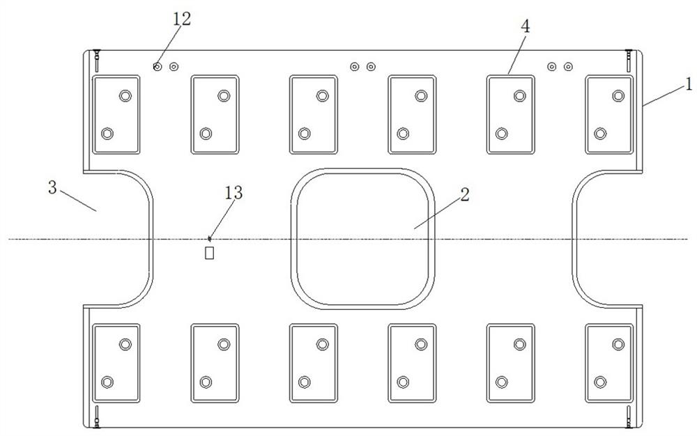
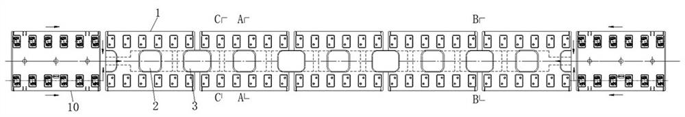
[0031] Example 1: as figure 1 As shown, the prefabricated frame plate in this embodiment is a prefabricated frame plate 1, the middle of the prefabricated frame plate 1 is provided with a hole 2 in the middle of the plate, and the two ends along the line direction are respectively provided with plate end holes 3. On the surface of the prefabricated frame plate 1 and at the positions on both sides of the opening 2 in the plate, there are respectively provided rail support platforms 4 arranged along the line direction, and each rail support platform 4 is used to carry the steel rails.

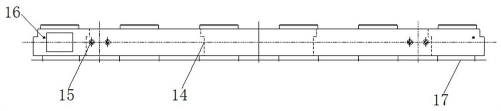
[0032] combine figure 1 and figure 2 As shown, various auxiliary structures or embedded parts can be arranged on the prefabricated frame plate 1 to improve its use effect or application range. like figure 2 As shown, a three-rail bracket mounting hole 12 can be provided on the surface side of the prefabricated frame plate 1 for installing the three-rail bracket when needed. A settlement obs...

Embodiment 2

[0044] Embodiment 2: as Figure 9 As shown in the figure, the prefabricated frame plate in this embodiment can also be applied to the drainage transition section on both sides of the floating plate. At this time, the prefabricated frame plate 1 is connected between the floating plate 11 and the conventional track plate, and the central water ditch is adopted. For drainage, the hole 2 in the plate and the hole 3 at the end of the plate can be used as dredging holes for the central water ditch. Under the above conditions, the plate seams can be designed with the same distance.

Embodiment 3

[0045] Example three: as Figure 10 and Figure 11 As shown, the prefabricated frame plate in this embodiment can also be applied to the anti-vibration track bed, and this form can be used when the anti-vibration track bed is located at both ends of the floating slab track bed. The prefabricated frame plate 1 is erected on the base 5 below, and a secondary pouring concrete 20 is arranged between the two, and a vibration damping pad 19 is arranged between the secondary pouring concrete 20 and the base 5 for vibration damping. A central water ditch 21 is opened in the middle of the track bed, and the prefabricated frame plate 1 covers the central water ditch 21 .


PUM


Abstract

The invention relates to the technical field of rail transit, in particular to a prefabricated frame plate and an application method thereof, open holes are formed in the plate middle and the plate end of the prefabricated frame plate respectively, notches are formed in the positions of the open holes in the plate middle and the open holes in the plate end of the prefabricated frame plate, and the notches are used for installing cover plates. The device has the advantages that the structure is simple and reasonable, and installation is convenient; the use is convenient, and particularly, the built-in pump room structure is convenient to maintain and overhaul; the ballast bed evacuation function is not influenced; the requirements of using working conditions such as a built-in pump room section and drainage transition sections on the two sides of the floating slab can be met, the application range is wide, the expansibility is high, and the method is suitable for popularization.

Description

technical field [0001] The invention relates to the technical field of rail transit, in particular to a prefabricated frame plate and an application method thereof. Background technique [0002] With the development of rail transit, in order to realize the drainage inside the tunnel, a built-in pump room is often set up. This built-in pump room reduces the risk of civil construction and reduces the overall cost of the project. The built-in pump room is a submersible set in the track bed structure. The pump is slotted at the design position of the ballast bed, and the pipeline attached to the pump is slotted and perforated in the ballast bed, so that the internal water is discharged through the built-in pump room composed of the water pump and the pipeline. However, in this process, the slotting or perforating construction of the ballast bed often destroys the structural strength of the ballast bed, and also affects the construction efficiency, and the construction quality is...

Claims


Application Information

Patent Timeline
Patent Type & Authority Applications(China)
IPC IPC(8): E01B1/00E01B2/00
CPCE01B1/00E01B1/008E01B2/00
Inventor 吴俊刘冬娅王宇航钱程
Owner CHINA RAILWAY SHANGHAI DESIGN INST GRP
Why Eureka
Try Eureka