Method and system for controlling separation time of electric control silicone oil fan

A technology of fan and silicone oil, which is used in the control of coolant flow, clutch, fluid clutch, etc., to achieve the effect of reducing the disengagement time

Active Publication Date: 2022-07-29
WEICHAI POWER CO LTD
View PDF6 Cites 0 Cited by
  • Summary
  • Abstract
  • Description
  • Claims
  • Application Information

AI Technical Summary

Problems solved by technology

[0007] In view of this, the present invention proposes a method and system for controlling the disengagement time of the electronically controlled silicon oil fan, aiming to solve how to prevent full meshing control of the electronically controlled silicon oil fan when the electronically controlled silicon oil fan enters the full mesh state, so as to The problem of reducing the detachment time of the electric silicon oil fan

Method used


Image

  • Method and system for controlling separation time of electric control silicone oil fan
  • Method and system for controlling separation time of electric control silicone oil fan
  • Method and system for controlling separation time of electric control silicone oil fan

Examples


Embodiment Construction

[0050] Exemplary embodiments of the present disclosure will be described in more detail below with reference to the accompanying drawings. While exemplary embodiments of the present disclosure are shown in the drawings, it should be understood that the present disclosure may be embodied in various forms and should not be limited by the embodiments set forth herein. Rather, these embodiments are provided so that the present disclosure will be more thoroughly understood, and will fully convey the scope of the present disclosure to those skilled in the art. It should be noted that the embodiments of the present invention and the features of the embodiments may be combined with each other under the condition of no conflict. The present invention will be described in detail below with reference to the accompanying drawings and in conjunction with the embodiments.

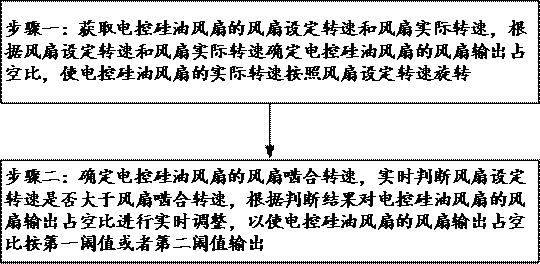
[0051] see image 3 As shown in the figure, the engine electronically controlled silicon oil clutch fan is controlle...


PUM


Abstract

The invention relates to the technical field of engines, and provides a method and system for controlling the separation time of an electric control silicone oil fan, and the method comprises the steps that the fan set rotating speed and the fan actual rotating speed of the electric control silicone oil fan are obtained, and the fan output duty ratio of the electric control silicone oil fan is determined according to the fan set rotating speed and the fan actual rotating speed; the fan meshing rotating speed of the electric control silicone oil fan is determined, whether the fan set rotating speed is larger than the fan meshing rotating speed or not is judged in real time, and the fan output duty ratio of the electric control silicone oil fan is adjusted in real time according to the judgment result so that the fan output duty ratio can be output according to the first threshold value or the second threshold value. The fan output duty ratio of the electric control silicone oil fan is adjusted in real time, when the electric control silicone oil fan reaches the highest rotating speed, the fan duty ratio is always kept to be switched between different threshold values at high frequency, it is ensured that silicone oil circulates in a critical saturation state, and when the required rotating speed of the fan is reduced, the fan is rapidly disengaged, and the service life of the fan is prolonged. And the separation time of the electric control silicone oil fan is greatly shortened.

Description

technical field [0001] The present invention relates to the technical field of engines, in particular, to a method and a system for controlling the disengagement time of an electronically controlled silicon oil fan. Background technique [0002] Silicone oil fan clutch (electronically controlled silicone oil clutch fan) uses silicone oil as a medium to transmit torque by shearing and viscous force of silicone oil. The speed of the fan is designed to ensure that the engine does not overheat when the operating conditions are the worst. Therefore, in the normal driving process of the vehicle, the speed of the fan should be controlled within an appropriate range, so as to reduce noise and improve engine economy. . For engine-driven fans, a fan clutch is usually used to control their speed. [0003] like figure 1 As shown, the working principle of the electronically controlled silicone oil clutch fan: the fan silicone oil enters the working chamber through the silicone oil por...

Claims


Application Information

Patent Timeline
Patent Type & Authority Applications(China)
IPC IPC(8): F16D35/02F01P7/04
CPCF16D35/024F01P7/042
Inventor 王云朱江苏杨新达孙楠楠
Owner WEICHAI POWER CO LTD
Why Eureka
Try Eureka