Light-emitting diode encapsulation method and jig

A technology of light-emitting diodes and packaging methods, applied in electrical components, circuits, semiconductor devices, etc., can solve problems such as uneven glue discharge, improve process efficiency, shorten detachment time, and accelerate downward flow.

Inactive Publication Date: 2012-11-21
ZHANJING TECH SHENZHEN +2
View PDF0 Cites 0 Cited by
  • Summary
  • Abstract
  • Description
  • Claims
  • Application Information

AI Technical Summary

Problems solved by technology

[0004] One of the purposes of the present invention is to provide a method for packaging light-emitting diodes that can improve the problem of uneven glue discharge at the beginning of packaging

Method used


Image

  • Light-emitting diode encapsulation method and jig
  • Light-emitting diode encapsulation method and jig
  • Light-emitting diode encapsulation method and jig

Examples


Embodiment Construction

[0016] Below in conjunction with accompanying drawing and embodiment the present invention is described in detail:

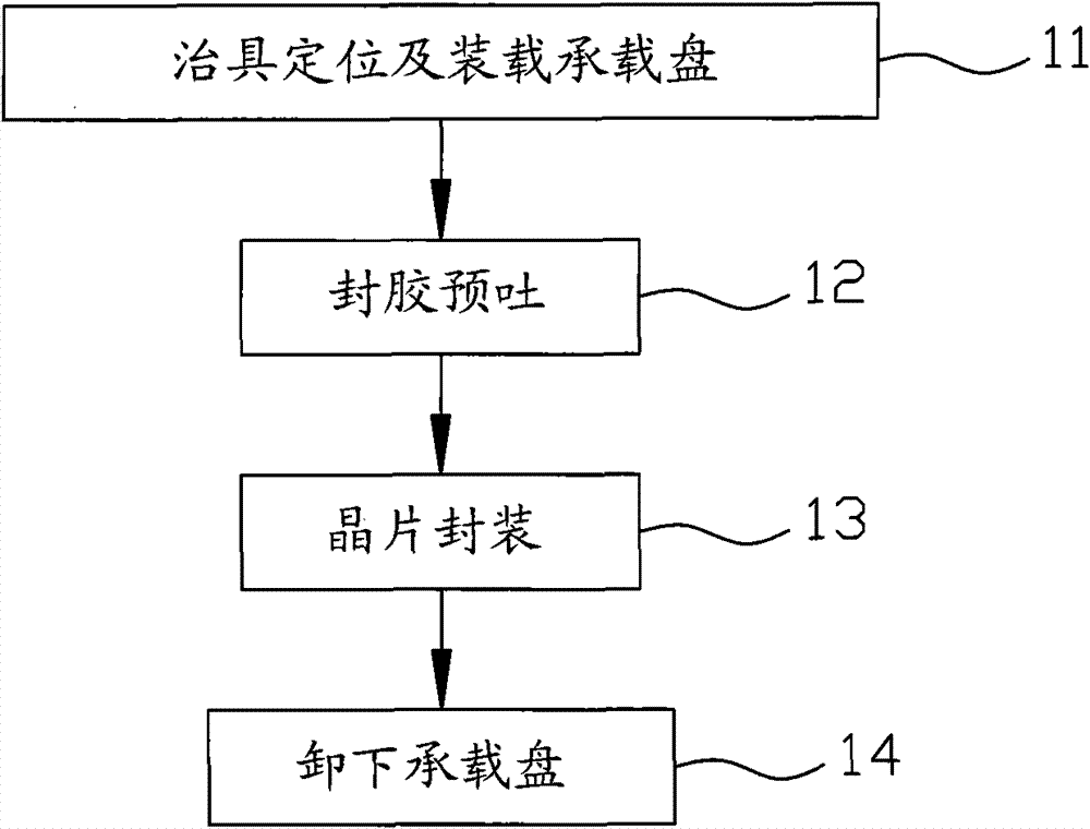
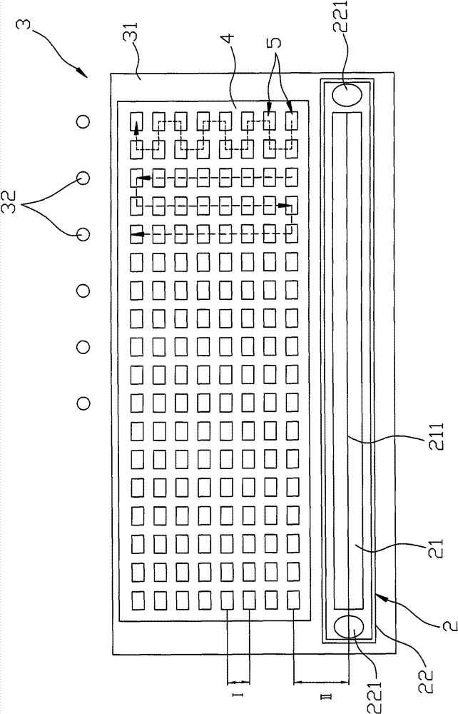
[0017] refer to Figure 1 ~ Figure 3 , a preferred embodiment of the LED packaging method of the present invention includes steps 11-14.

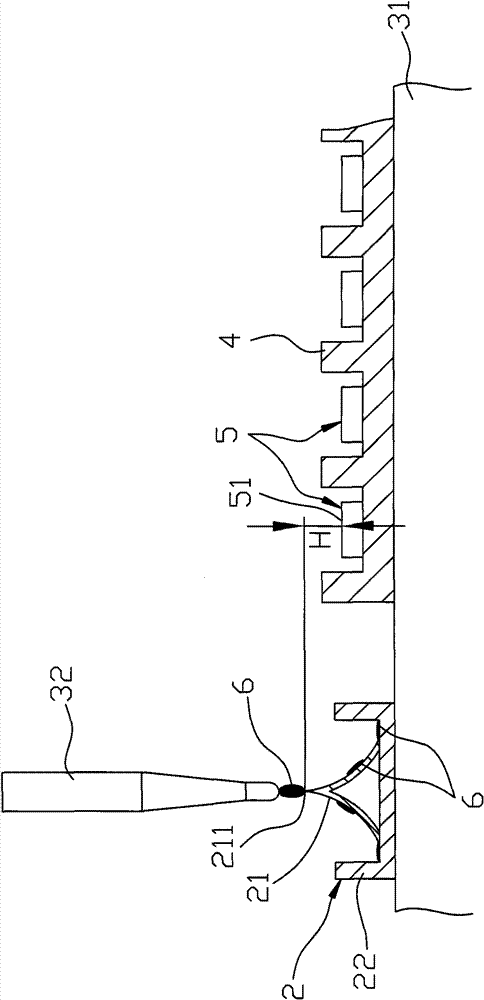
[0018] Step 11 is jig positioning and loading tray: a jig 2 is placed on a workbench 31 of a packaging machine 3, wherein the jig 2 includes a shunt rack 21, and a collection rack 21 for the shunt rack 21 The tray 22, the distribution frame 21 has a receiving portion 211 extending along a first direction of the worktable 31, and a section of the distribution frame 21 along a second direction perpendicular to the first direction of the worktable 31 is It is narrow at the top and wide at the bottom. In this embodiment, the cross-section of the distribution frame 21 along the second direction is a triangle with a sharp top and a wide bottom, and the two hypotenuses are in a concave arc shape. The collection tray 22 is used to ...


PUM


Abstract

The invention discloses a light-emitting diode (LED) encapsulation method, which comprises the following steps of: placing a jig on a workbench, wherein the jig comprises an adapting part extended along a first direction; placing at least one bearing tray for bearing LED elements arranged in multiple columns on the workbench, wherein the LED elements of two adjacent columns have a spacing distance along a second direction, the adapting part and one column of closest LED elements have a distance along the second direction, and the ratio of the distance to the spacing distance is not more than 3.5; and pre-jetting a sealant amount enough for encapsulating the LED elements by a plurality of glue needles to stick the LED elements on the adapting part, and encapsulating the LED elements respectively. Therefore, several previously encapsulated LED elements can avoid incomplete encapsulation due to non-uniform glue throughput so as to achieve the effects of promoting the encapsulation yield and increasing the coherent infrared energy (CIE) concentration degree of the LED.

Description

technical field [0001] The invention relates to a light-emitting diode, in particular to a method for packaging a light-emitting diode and a fixture thereof. Background technique [0002] In the general LED packaging process, the glue injection device of the packaging machine is used to dispense glue on the LED elements on the carrier plate, and a light emitting diode will be formed after the packaging is completed; however, before dispensing, if the glue injection device has been processed For example, when the syringe or needle is replaced due to blockage, it is necessary to spit the glue in advance after the parts are replaced, so as to compress the sealant and discharge the air bubbles, so as to avoid the air bubbles in the sealant and make the packaged LED components unsuitable. Good product. Or, when the packaging machine has a long standby time due to the replacement of the carrier plate, the sealing glue at the needle opening will harden, and it will no longer be th...

Claims


Application Information

Patent Timeline
Patent Type & Authority Patents(China)
IPC IPC(8): H01L33/52
Inventor 孔维江曾嘉庆张庭豪
Owner ZHANJING TECH SHENZHEN
Why Eureka
Try Eureka