Heat exchanger and heat exchanger system

A heat exchanger and thermal conductivity technology, which is applied to indirect heat exchangers, heat exchanger types, heat storage equipment, etc. , The effect of increasing the cooling capacity and reducing the heat

Pending Publication Date: 2020-12-15
GUANGZHOU UNIVERSITY
View PDF0 Cites 0 Cited by
  • Summary
  • Abstract
  • Description
  • Claims
  • Application Information

AI Technical Summary

Problems solved by technology

However, this liquefaction time is often relatively long, which results in a large loss of cooling capacity for transmission

Method used


Image

  • Heat exchanger and heat exchanger system
  • Heat exchanger and heat exchanger system
  • Heat exchanger and heat exchanger system

Examples


Embodiment 1

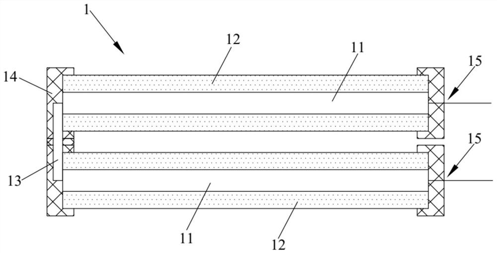
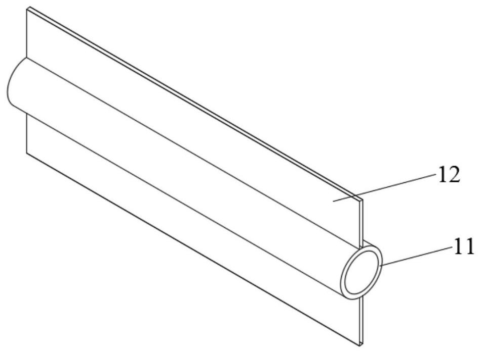
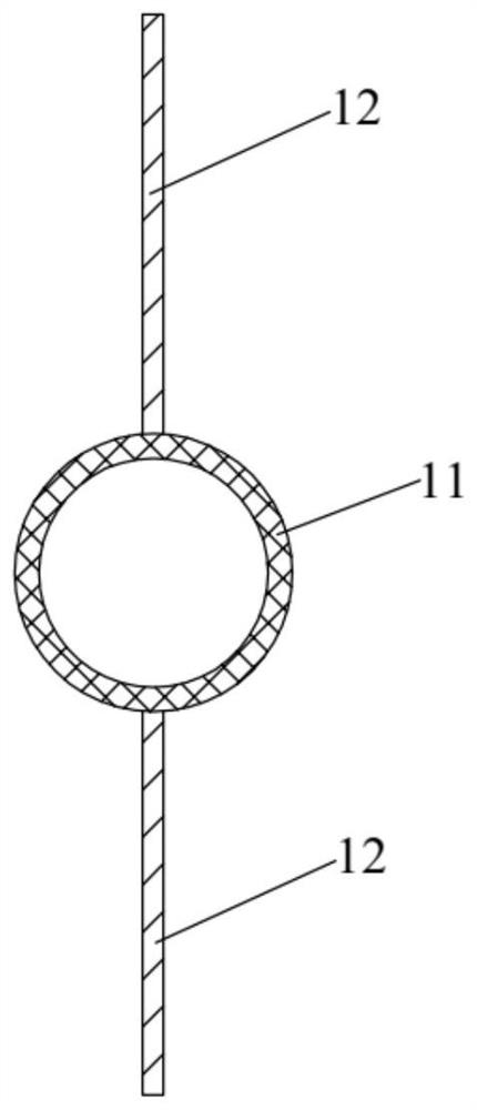
[0038] Such as Figure 1-Figure 3 As shown, this embodiment provides a heat exchanger. The heat exchanger 1 includes a heat exchange assembly, and the heat exchange assembly includes a row tube 11 and fins 12. The row tube 11 can be filled with brine or heat carrier. The fins 12 are arranged on the outer wall of the row pipe 11 , and the height of the fins 12 extends along the radial direction of the row pipe 11 . The thermal conductivity of the fins 12 is smaller than that of the row pipes 11 .

[0039] In the heat exchanger provided in this embodiment, when the cooling is released, the brine is passed through the exhaust tube 11 to perform cooling. Since the thermal conductivity of the fins 12 is smaller than that of the exhaust tubes 11, the phase on the fins 12 The growth rate of the solid substance is very slow, and the fins 12 have a certain height. The phase-change solid substances on both sides of the pipe 11 generally cannot cross the top of the fin 12 to connect int...

Embodiment 2

[0054] Such as Figure 4 As shown, this embodiment provides a heat exchanger system, including the heat exchanger 1 provided in Embodiment 1, and also includes a switching valve 5, a low-temperature cold source and a high-temperature heat source 6, and the low-temperature cold source and high-temperature heat source 6 pass through the switching valve 5 It is connected with the row pipe 11, so as to pass brine or heating agent into the row pipe 11. Specifically, in this embodiment, the switching valve 5 is a four-way valve. In the cooling condition, the low-temperature cooling source is communicated with the exhaust pipe 11 by switching the switching valve 5, so that the brine can be introduced into the exhaust pipe 11; The heat source communicates with the row pipe 11 to feed heat carrier into the row pipe 11 .

Embodiment 3

[0056] Such as Figure 5 As shown, this embodiment provides a heat exchanger system, including the heat exchanger 1 provided in Embodiment 1, and also includes a cold storage tank 2, a filter screen 3, a circulation assembly 4, a switching valve 5, and a low-temperature cold source and a high-temperature heat source 6 . Water and ice are housed in the cold storage tank 2 . The filter screen 3 is installed on the top of the cold storage tank 2 and immersed in water. The circulation assembly 4 comprises a circulation pipeline 41, a valve 42, a water pump 43 and a water distributor nozzle 44. The inlet 411 of the circulation pipeline 41 is inserted in the water of the cold storage tank 2, and the inlet 411 is positioned above the filter screen 3. The valve 42 and The water pumps 43 are installed on the circulation pipeline 41 , and the outlet 412 of the circulation pipeline 41 communicates with the water distributor nozzle 44 , and the water distributor nozzle 44 is arranged at...


PUM

PropertyMeasurementUnit
thermal conductivityaaaaaaaaaa

Abstract

The invention relates to the technical field of heat exchangers, and discloses a heat exchanger and a heat exchanger system. The heat exchanger comprises calandrias and fins, a secondary refrigerant or a heat-carrying agent can be introduced into the calandrias, the fins are arranged on the outer walls of the calandrias, the height of the fins extends in the radial direction of the calandrias, andthe heat conductivity coefficient of the fins is less than that of the calandrias. According to the heat exchanger, the heat conductivity coefficient of the fins is lower, the fins have the isolationeffect, phase-change solid substances on the two sides of the calandrias are separated under the cold release working condition, the phase-change solid substances are prevented from annularly wrapping around the calandrias, the phase-change solid substance separation time under the heating working condition is shortened, input heat is reduced, the cold release amount in the cold release-heating period is improved, due to the fact that the phase-change solid substances on the calandrias can be rapidly removed, the thermal resistance formed by the phase-change solid substances can be limited ata lower value, and the cold release and heat exchange efficiency of the heat exchanger is greatly improved.

Description

technical field [0001] The invention relates to the technical field of heat exchangers, in particular to a heat exchanger and a heat exchanger system. Background technique [0002] With the improvement of people's living standards, the demand for energy is also increasing, such as central air-conditioning refrigeration, heating in northern winter, logistics cold supply chain, large-scale heat storage and cold storage, etc. The transmission of cold and heat here involves the use of heat exchangers. For conventional fluid medium heat transfer, high heat transfer efficiency can be achieved by increasing the thermal conductivity of heat exchanger materials, increasing the heat transfer area, and increasing the flow velocity of conventional fluids, which can respond to the national requirements for energy saving and emission reduction . However, some heat exchanger systems involve the phase change of the medium, especially the heat transfer system of gas-solid and liquid-solid ...

Claims


Application Information

Patent Timeline
Patent Type & Authority Applications(China)
IPC IPC(8): F28D1/053F28F1/20F28F21/08F28F21/06F28D20/02
CPCF28D1/053F28D20/021F28F1/20F28F21/062F28F21/081Y02E60/14
Inventor 陈奇良李峰郝海青周孝清毛凯姜恒
Owner GUANGZHOU UNIVERSITY
Why Eureka
Try Eureka