Drying and digesting device

A drying and sealing box technology, which is applied to heating devices, drying chambers/containers, drying solid materials, etc., can solve problems such as low heat exchange efficiency

Pending Publication Date: 2022-07-29
郑州长城冶金设备有限公司
View PDF7 Cites 0 Cited by
  • Summary
  • Abstract
  • Description
  • Claims
  • Application Information

AI Technical Summary

Problems solved by technology

[0005] The purpose of the present invention is to provide a dry digestion device to solve the technical problem of low heat exchange efficiency of heating components in the prior art.

Method used


Image

  • Drying and digesting device
  • Drying and digesting device
  • Drying and digesting device

Examples


specific Embodiment 1

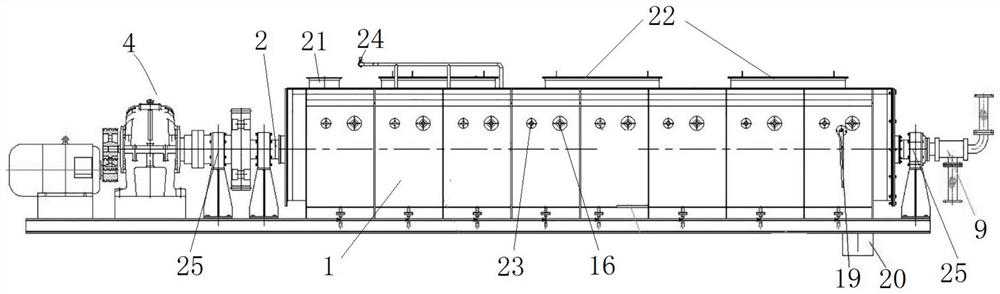
[0032] like Figure 1 to Figure 5 As shown, the drying and digesting device includes a sealing box 1, a power device 4 and two rotating shafts 2 rotatably assembled in the sealing box 1. The sealing box 1 extends forward and backward, and the power device 4 is arranged at the front end of the sealing box 1 and is connected with the two rotating shafts. 2. The transmission connection, the power device 4 is used to drive the rotating shaft 2 to rotate, and the two rotating shafts 2 also extend back and forth and are parallel to each other. The power device 4 in this embodiment is a motor and its configured accelerator. Both are provided with a rotating bearing seat 25, the bearing seat 25 supports the rotating shaft 2 and ensures that the rotating shaft 2 is horizontal. Components such as the power unit 4 and the bearing seat 25 are all in the prior art, and will not be repeated here.

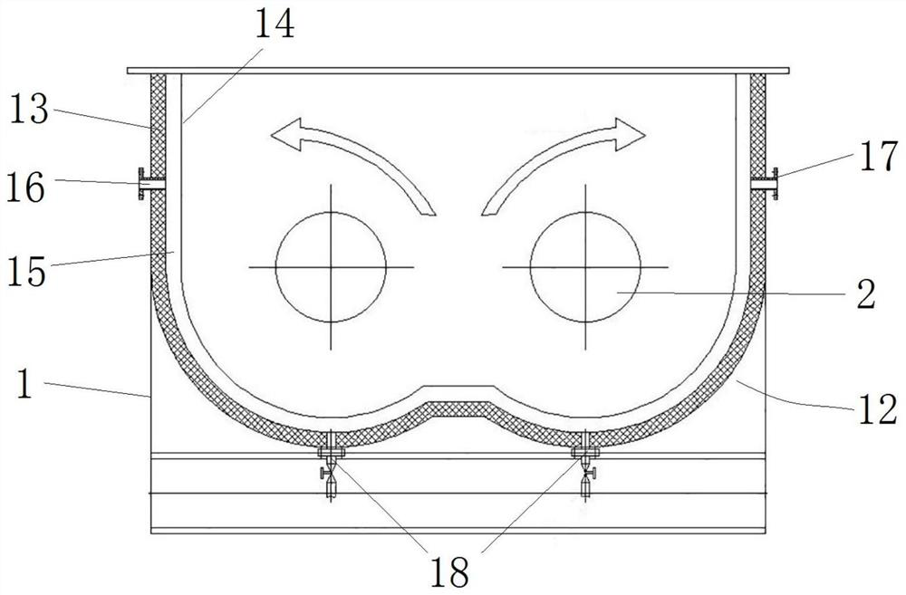
[0033] like figure 1 and figure 2 As shown, the sealing box 1 is a rectangular box structu...

specific Embodiment 2

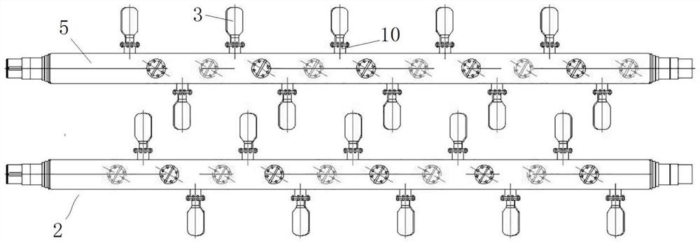
[0044] The difference from Embodiment 1 is that in Embodiment 1, both the air inlet and the air outlet on the rotating shaft 2 are provided at the rear end of the rotating shaft 2 . In this embodiment, the air inlet of the inner cylinder 6 is set at the front end of the inner cylinder 6 , the air outlet of the outer cylinder 5 is set at the rear end of the outer cylinder 5 , and the air inlet and the air outlet are respectively set at both ends of the rotating shaft 2 . In other embodiments, the rotating shaft can also be a structure with closed ends, that is, the front and rear ends of the inner and outer cylinders are closed, and the air inlet and outlet at this time can be provided on the cylinder walls of the inner and outer cylinders. .

specific Embodiment 3

[0046] The difference from Example 1 is that in Example 1, the drying and digesting device includes a rotary joint 9 disposed on the rear side of the sealing box 1 , and the rotary joint 9 is a three-way joint. In this embodiment, the rotary joint is replaced with an air valve. In other embodiments, the rotary joint is eliminated, and the rear end of the rotary shaft extends out of the bearing seat and is directly connected to the trachea, and the trachea is used to connect the ventilation equipment.


PUM


Abstract

The invention relates to the technical field of material digestion, and aims at providing a drying digestion device to solve the technical problem that a digestion device in the prior art is provided with a heating assembly and is low in heat exchange efficiency. The drying digestion device comprises a sealing box and a rotating shaft rotationally assembled in the sealing box, rotating blades are uniformly distributed on the rotating shaft, the rotating shaft comprises an outer cylinder and an inner cylinder assembled in the outer cylinder, and an annular interval is formed between the outer cylinder and the inner cylinder; hollow sleeves are uniformly distributed on the peripheral surface of the outer cylinder, extend in the radial direction outside the rotating shaft and are used for fixing the rotating blades; a plurality of heat conduction pipes for communicating an inner cavity of the inner cylinder with inner cavities of the sleeves are arranged on the inner cylinder, the heat conduction pipes are used for guiding hot steam in the inner cylinder into the sleeves, and the inner cavities of the sleeves are communicated with the annular intervals; an air inlet is formed in the inner cylinder and used for inputting a heat exchange medium, and an air outlet is formed in the outer cylinder and used for guiding out the heat exchange medium which flows into the sleeve at the annular interval and is subjected to heat exchange.

Description

technical field [0001] The invention relates to the technical field of material digestion, in particular to a dry digestion device. Background technique [0002] In the dehydration and stirring processing of materials, especially the stirring processing of quicklime materials, it is usually necessary to use a drying and digesting device to quickly and fully digest the quicklime. , stirring, digestion, drying and digestion device vaporizes and escapes the moisture (generally refers to moisture or other volatile liquid components) in the material by heating and stirring, so as to obtain solid materials with a specified moisture content. According to the operating pressure of the device, the digestion device is usually divided into two types: atmospheric pressure device and vacuum device. Both types of digestion devices can quickly digest materials to obtain the required processing materials. [0003] The Chinese utility model patent with the authorization announcement number ...

Claims


Application Information

Patent Timeline
Patent Type & Authority Applications(China)
IPC IPC(8): F26B11/16F26B23/10F26B25/04F26B25/06F28B9/08
CPCF26B11/16F26B23/10F26B25/008F26B25/04F26B25/06F28B9/08
Inventor 郭奎元张文志李永卓
Owner 郑州长城冶金设备有限公司
Why Eureka
Try Eureka