
Direction-adjustable sensor mounting seat and mounting method thereof

A technology of sensors and mounts, which is applied in the field of adjustable sensor mounts, can solve problems such as inability to obtain effective inversion parameters, inability to correct bolt installation errors, and directional errors in measurement results, so as to facilitate mass processing, Accurately adjust the effect of reliable curing and reduce the requirements of processing accuracy

Pending Publication Date: 2022-07-29
NORTHWEST INST OF NUCLEAR TECH
View PDF7 Cites 0 Cited by
  • Summary
  • Abstract
  • Description
  • Claims
  • Application Information

AI Technical Summary

Problems solved by technology

[0005] The purpose of the present invention is to solve the technical problem that the existing field chemical explosion experiment measurement sensor mounting seat is a fixed structure, and the installation error of the anchor rod cannot be corrected, resulting in directional errors in the measurement results and the inability to obtain effective inversion parameters. To provide an adjustable sensor mount and its implementation method

Method used


Image

  • Direction-adjustable sensor mounting seat and mounting method thereof
  • Direction-adjustable sensor mounting seat and mounting method thereof
  • Direction-adjustable sensor mounting seat and mounting method thereof

Examples


Embodiment Construction

[0055] The present invention will be further described in detail below in conjunction with the accompanying drawings

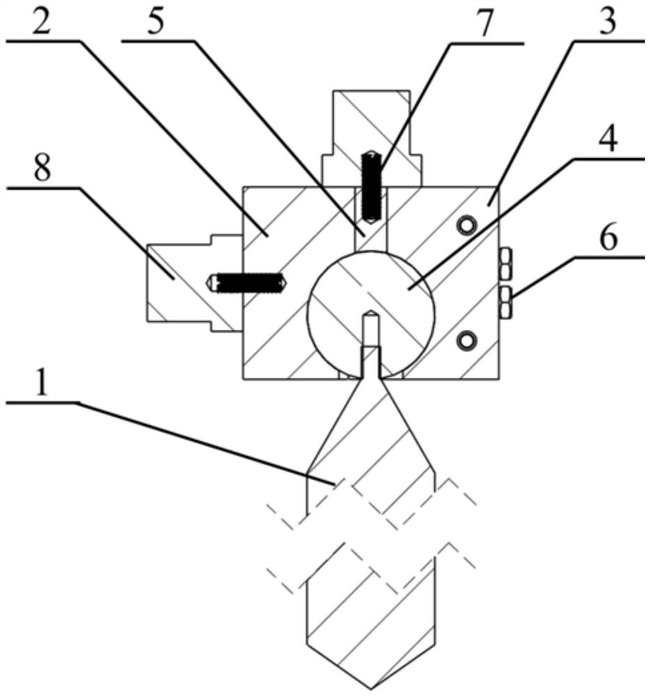
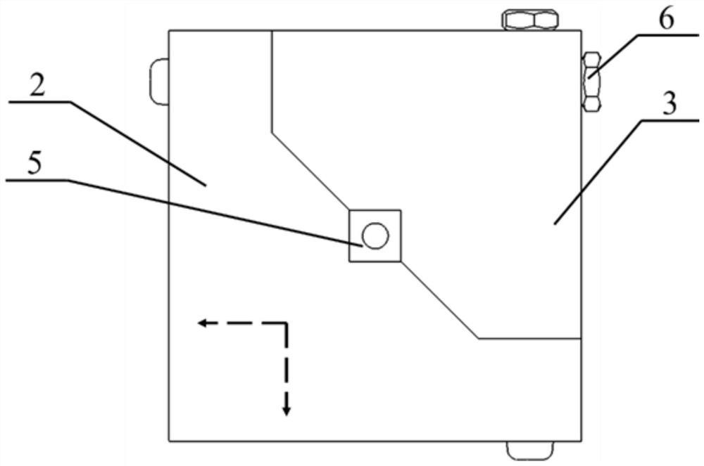
[0056] like figure 1 , figure 2 As shown in the figure, the present invention provides an orientable sensor mounting seat. The overall structure includes an anchor rod 1 and a positioning unit. The positioning unit includes a first module 2, a second module 3, a spherical base 4, a positioning pin 5, and a bolt. Assembly 6 and three connecting screws 7.

[0057] The top of the anchor rod 1 is provided with threads, which are fixedly connected with the screw holes at the bottom of the spherical base 4 through threads. The lower part of the threads of the anchor rod 1 is provided with a conical transition section. This structural design increases the angle adjustment range of the mounting seat.

[0058] The first module 2 and the second module 3 are fixedly connected by bolt assemblies 6 to form a cube structure, and the tightening direction of the bolt assem...


PUM


Abstract

The invention relates to a direction-adjustable sensor mounting seat and a mounting method thereof. The technical problems that an existing sensor installation base is of a fixed structure, anchor rod installation errors cannot be corrected, errors exist in measurement results, and effective inversion parameters cannot be obtained are solved. The sensor mounting seat comprises an anchor rod and a positioning unit, wherein the positioning unit comprises a first module, a second module, a spherical base, a positioning pin and three connecting screw rods; the first module and the second module are connected to form a cube structure; hemispherical groove structures are formed in the lower portions of the first module and the second module, a spherical cavity is formed in the cube structure, and the spherical base is located in the spherical cavity; a positioning groove is formed in the center of the cube structure, the positioning pin is located in the positioning groove, and a screw hole is formed in the positioning pin; screw holes are formed in two mounting surfaces of the first module; the screw hole is used for installing a connecting screw, and the outer end of the connecting screw is used for installing a sensor.

Description

technical field [0001] The invention relates to a sensor installation device used for explosion experiment testing, in particular to an orientable sensor installation seat and an installation method thereof. Background technique [0002] Explosion mechanics experiment is one of the important contents to study the propagation and evolution law of blast stress wave in rock and soil medium and the damage effect of nearby rock and soil. When the explosion occurs, the stress wave will be excited in the surrounding medium and propagate outward, and the medium will have regular motion on the propagation path. By measuring the kinematic characteristics of materials at different positions, the attenuation law of the path medium to the stress waveform can be obtained. [0003] At present, the rock bolt anchoring process is often used to couple the movement of the near-ground medium in the field chemical explosion experiment. By installing the sensor mount and related sensors on the r...

Claims


Application Information

Patent Timeline
Patent Type & Authority Applications(China)
IPC IPC(8): G01D11/30G01D11/16
CPCG01D11/30G01D11/16
Inventor 李凯凯卢强张向荣方厚林李耀龙张亮永丁洋刘赟哲
Owner NORTHWEST INST OF NUCLEAR TECH
Learn More