Motor stator temperature measuring method and device and vehicle

A motor stator, temperature measurement technology, applied in the direction of measuring device, temperature measurement of moving solids, thermometer test/calibration, etc., can solve the problems of unbalanced cooling effect of motor stator, large temperature deviation, different motor stators, etc.

Pending Publication Date: 2022-07-29
GREAT WALL MOTOR CO LTD
View PDF0 Cites 0 Cited by
  • Summary
  • Abstract
  • Description
  • Claims
  • Application Information

AI Technical Summary

Problems solved by technology

In the existing electric vehicles on the market, the temperature of the driving motor is directly determined by reading the sampling value of the temperature sensor of the motor stator, but in fact, as the vehicle condition changes, the speed of the driving motor also changes in real time, and That is to say, when the speed of the vehicle rotor is higher, the cooling effect of the surrounding medium such as coolant on the motor stator is more and more unbalanced, and the temperature of different regions of the motor stator may be different
Therefore, limited by the structure of the controller, the layout of the cooling pipeline, the position of the temperature sensor, and the change of the vehicle speed, the temperature at a certain position of the stator measured by the temperature sensor of the stator has a large deviation from the current actual overall temperature of the stator.

Method used


Image

  • Motor stator temperature measuring method and device and vehicle
  • Motor stator temperature measuring method and device and vehicle
  • Motor stator temperature measuring method and device and vehicle

Examples


Embodiment Construction

[0057] The specific embodiments of the present disclosure will be described in detail below with reference to the accompanying drawings. It should be understood that the specific embodiments described herein are only used to illustrate and explain the present disclosure, but not to limit the present disclosure.

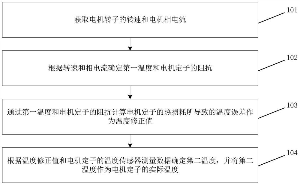
[0058] figure 1 It is a flow chart of a method for measuring the temperature of a motor stator according to an exemplary embodiment of the present disclosure. like figure 1 As shown, the method includes steps 101 to 104 .

[0059] In step 101, the rotational speed of the motor rotor and the motor phase current are obtained. The rotational speed and the motor phase current can be obtained directly from the motor through corresponding sensors, or can be obtained from the vehicle through a controller area network (CAN network).

[0060] In step 102, the first temperature and the impedance of the motor stator are determined according to the rotational speed and the phas...


PUM


Abstract

The invention relates to a motor stator temperature measuring method and device and a vehicle. The method comprises the steps of obtaining the rotating speed of a motor rotor and motor phase current; first temperature and impedance of a motor stator are determined according to the rotating speed and the phase current, and the first temperature and the impedance of the motor stator are calibration values; calculating a temperature error caused by heat loss of the motor stator through the first temperature and the impedance of the motor stator as a temperature correction value; and determining a second temperature according to the temperature correction value and temperature sensor measurement data of the motor stator, and taking the second temperature as an actual temperature of the motor stator. Therefore, the measured data measured by the temperature sensor of the motor stator can be corrected by measuring the rotating speed and the phase current of the motor, so that the obtained actual temperature can reflect the temperature of the driving motor more accurately; the problem of inaccurate temperature measurement of the motor stator caused by the rotating speed of the motor and the set position of the temperature sensor is avoided.

Description

technical field [0001] The present disclosure relates to the field of vehicle motors, and in particular, to a method, device and vehicle for measuring the temperature of a motor stator. Background technique [0002] In pure electric drive / hybrid drive vehicles, the motor temperature is a crucial parameter during the operation of the vehicle. Only when the motor works within a certain reasonable range can the motor normally provide a power source for the entire vehicle. The motor temperature is usually used as the basis for the control command, so the reported value of the motor temperature needs to reflect the actual temperature of the motor as much as possible to ensure that the thermal management control strategy is effective. [0003] The fixed part of a common motor is called the stator, and the rotating part is usually called the rotor. In the existing electric vehicles on the market, the temperature of the drive motor is directly determined by reading the sampling val...

Claims


Application Information

Patent Timeline
IPC IPC(8): H02P29/60G01K13/08G01K15/00
CPCH02P29/60G01K13/08G01K15/005
Inventor 张哲
Owner GREAT WALL MOTOR CO LTD
Why Eureka
Try Eureka