Intelligent bullet cabinet with anti-theft device

An anti-theft device and bullet cabinet technology, which is applied in the field of bullet cabinets, can solve the problems of not being able to report to the police in time, and achieve the effect of preventing wear and tear and preventing backward dumping

Active Publication Date: 2022-08-02
JIANGXI EQUIP INDAL GROUP GREAT INSURANCENT
View PDF12 Cites 3 Cited by
  • Summary
  • Abstract
  • Description
  • Claims
  • Application Information

AI Technical Summary

Problems solved by technology

[0005] In order to overcome the shortcomings of the existing technology that cannot report in time, the technical problem to be solved is: to provide an intelligent bullet cabinet with an anti-theft device that can report in time

Method used


Image

  • Intelligent bullet cabinet with anti-theft device
  • Intelligent bullet cabinet with anti-theft device
  • Intelligent bullet cabinet with anti-theft device

Examples


Embodiment 1

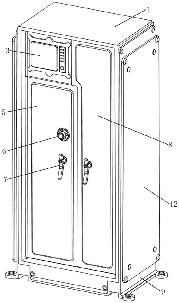
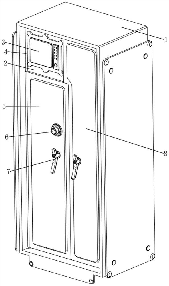
[0038] An intelligent bullet cabinet with anti-theft device, refer to Figure 1-7 , including an outer frame body 1, an inner frame body 2, a display screen 3, a fixed rod 4, a first cover plate 5, a combination lock 6, a handle 7, a second cover plate 8, an unloading mechanism 9 and an alarm mechanism 10. Inside the frame body 1 is an inner frame body 2, a display screen 3 is arranged on the upper left front side of the inner frame body 2, and fixing rods 4 are provided on the left and right sides of the front side of the inner frame body 2. A first cover plate 5 is provided. The upper right front side of the first cover plate 5 is provided with a combination lock 6. The combination lock 6 is electrically connected to the display screen 3, and the combination lock 6 is electrically connected to the first cover plate 5. The fixing rod 4 is rotatably provided with a second cover plate 8, the first cover plate 5 is in contact with the second cover plate 8, the first cover plate ...

Embodiment 2

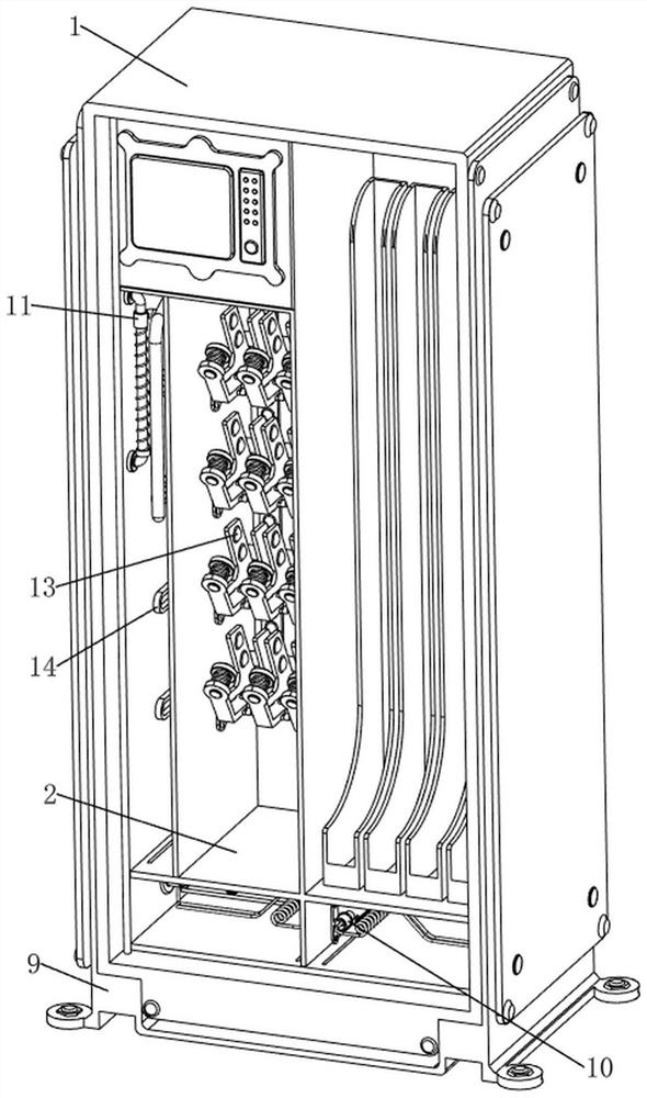
[0043] On the basis of Example 1, refer to figure 2 , Figure 8 , Figure 9 and Figure 10 , and also includes a locking mechanism 11, the locking mechanism 11 includes a fourth fixing column 111, a fifth fixing column 112, a motor 113, a reel 114, a pulling rope 115, a sixth fixing column 116, a limit rod 117, a latch 118, the second sliding rod 119, the second sliding sleeve 1110 and the third linear spring 1111, a fourth fixing column 111 is arranged on the upper part of the second fixing column 105 on the left side, and a fifth fixing column is arranged on the left side of the fourth fixing column 111 112. The motor 113 is fixedly connected to the upper part of the fifth fixing column 112 by bolts, the sixth fixing column 116 is arranged on the left side of the top of the fourth fixing column 111, and the upper right side of the sixth fixing column 116 is rotatably provided with a reel 114, which can be wound around. The right side of the wire pulley 114 is connected w...


PUM


Abstract

The invention relates to a bullet cabinet, in particular to an intelligent bullet cabinet with an anti-theft device. The intelligent bullet cabinet with the anti-theft device can give an alarm in time. An intelligent bullet cabinet with an anti-theft device comprises an outer frame body, an inner frame body, a display screen, fixing rods, a first cover plate, a coded lock, a second cover plate and the like, the inner frame body is arranged in the outer frame body, the display screen is arranged on the upper portion of the left front side of the inner frame body, the fixing rods are arranged on the left side and the right side of the front side of the inner frame body, and the first cover plate is rotationally arranged on the fixing rod on the left side; a coded lock is arranged on the upper portion of the right front side of the first cover plate and electrically connected with the display screen, and a second cover plate is rotationally arranged on the fixing rod on the right side. The first electric conductor moves backwards to be in contact with the second electric conductor for electric conduction, then the alarm is started through the electric wire on the front side, the alarm makes a sound to warn criminals, and meanwhile the alarm controls electronic alarm equipment in an external monitoring room to give an alarm through wireless signals.

Description

technical field [0001] The invention relates to a bullet cabinet, in particular to an intelligent bullet cabinet with an anti-theft device. Background technique [0002] Bullets are very dangerous. Careless use will cause serious consequences. In order to avoid using bullets during non-duty or training, bullet cabinets are required to store and control bullets. [0003] Patent publication number CN113017305A discloses an intelligent bullet cabinet with protection function. The technical problem of the invention is to provide a smart bullet locker with a protection function that can avoid gun theft. The technical implementation of the invention is: an intelligent bullet cabinet with a protection function, including a bullet cabinet and a first rotating shaft, the first rotating shaft is rotatably installed on both sides of the bullet cabinet; the cabinet door, the first rotating shaft A cabinet door is fixedly connected to a rotating shaft. The invention can identify the f...

Claims


Application Information

Patent Timeline
Patent Type & Authority Applications(China)
IPC IPC(8): A47B81/00A47B96/00A47B97/00G08B13/22G08B3/10G08B25/10E05B47/00E05B15/00E05B15/10E05B15/02E05B65/44E05B17/22E05B17/20
CPCA47B81/005A47B96/00A47B97/00G08B13/22G08B3/10G08B25/10E05B47/0012E05B47/026E05B15/00E05B15/10E05B15/0205E05B65/44E05B17/22E05B17/2092
Inventor 邹小兵
Owner JIANGXI EQUIP INDAL GROUP GREAT INSURANCENT
Why Eureka
Try Eureka