
Automatic grooving device

An automatic and slitting technology, applied in the direction of feeding device, positioning device, storage device, etc., can solve the problem of low efficiency of the slotting process, and achieve the effect of improving processing efficiency and shortening the punching time

Pending Publication Date: 2022-08-02
SHEN ZHEN TOP LINK TECH CO LTD
View PDF0 Cites 1 Cited by
  • Summary
  • Abstract
  • Description
  • Claims
  • Application Information

AI Technical Summary

Problems solved by technology

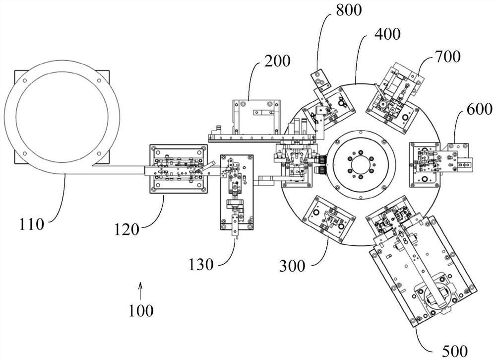
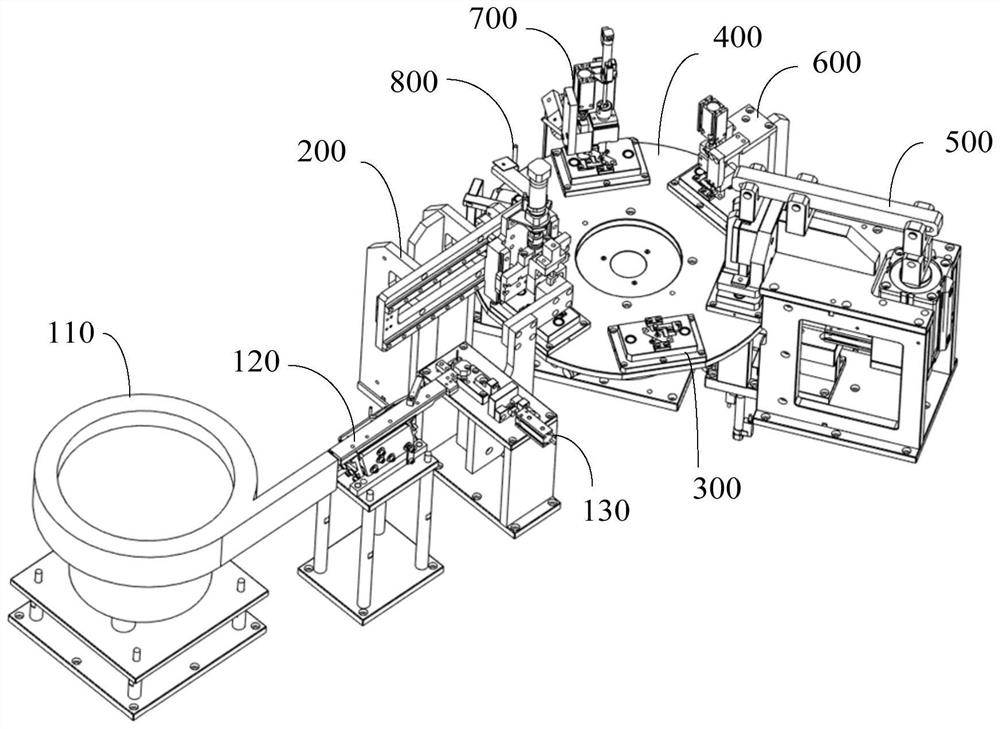
[0004] The main purpose of the present invention is to propose an automatic slotting device, which aims to solve the problem of low efficiency of the existing slotting process

Method used


Image

  • Automatic grooving device
  • Automatic grooving device
  • Automatic grooving device

Examples


Embodiment Construction

[0062] The technical solutions in the embodiments of the present invention will be clearly and completely described below with reference to the accompanying drawings in the embodiments of the present invention. Obviously, the described embodiments are only a part of the embodiments of the present invention, but not all of the embodiments. Based on the embodiments of the present invention, all other embodiments obtained by those of ordinary skill in the art without creative efforts shall fall within the protection scope of the present invention.

[0063]It should be noted that if there are directional indications (such as up, down, left, right, front, back, etc.) involved in the embodiments of the present invention, the directional indications are only used to explain a certain posture (as shown in the accompanying drawings). If the specific posture changes, the directional indication also changes accordingly.

[0064] In addition, if there are descriptions involving "first", "...


PUM


Abstract

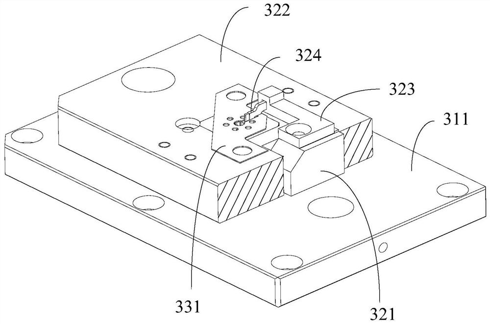
The invention discloses an automatic grooving device which comprises a carrier, a feeding mechanism, a punch and a grooving driving assembly, a workpiece is placed through the carrier, and the grooving driving assembly drives the punch to punch into a cutter set through the cutter set in the carrier and the punch matched with the cutter set. And the thin-wall part of the workpiece between the cutter group and the punch is punched, so that the slotting of the workpiece is realized. And the feeding mechanism is used for feeding and / or discharging the workpieces, so that full-automatic slotting of the workpieces is realized. Compared with existing saw blade machining equipment and machine tool machining equipment, the device can machine a plurality of grooves in the workpiece at the same time in a punching mode, the punching duration is extremely short, and the machining efficiency is greatly improved.

Description

technical field [0001] The invention relates to the field of automation equipment, in particular to an automatic slotting device. Background technique [0002] POGO-PIN connectors are now commonly used in electronic devices, which are generally composed of needle tubes, needle shafts, and springs. In the environment where POGO-PIN is constantly updated and the technology is not upgraded, its parts also change accordingly. The needle tube is a common thin-walled tube made of brass, and the end face of the thin-walled tube has different numbers of grooves. However, there are also many technical difficulties in the slotting of thin-walled tubes. For example, the parts of thin-walled tubes are very small, and the slotting dimensions of thin-walled tubes require high precision. In order to overcome these difficulties, corresponding mechanical equipment and manufacturing processes have been produced one after another. [0003] At present, the industry mostly uses mechanical equip...

Claims


Application Information

Patent Timeline
Patent Type & Authority Applications(China)
IPC IPC(8): B21D17/02B21D43/00
CPCB21D17/02B21D43/006Y02P70/50
Inventor 孙伯羽邓剑东周延河吴宏治
Owner SHEN ZHEN TOP LINK TECH CO LTD
Learn More