Hatch coaming structure of ultra-large container ship

A container, super-large technology, applied in the direction of ship hatches/hatch, hull, ship construction, etc., can solve the problems of no design sealing structure and easy water seepage.

Active Publication Date: 2022-08-02
JIANGSU YANGZI XINFU SHIPBUILDING CO LTD
View PDF6 Cites 0 Cited by
  • Summary
  • Abstract
  • Description
  • Claims
  • Application Information

AI Technical Summary

Problems solved by technology

[0005] In order to overcome the disadvantages that the existing ship hatch enclosure structure generally does not have a sealing structure and is prone to water seepage when encountering heavy rain or waves, the purpose of the present invention is to provide an ultra-large container that can prevent water from seeping into the ship cabin Hatch coaming structure

Method used


Image

  • Hatch coaming structure of ultra-large container ship
  • Hatch coaming structure of ultra-large container ship
  • Hatch coaming structure of ultra-large container ship

Examples


Embodiment 1

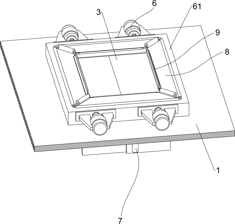
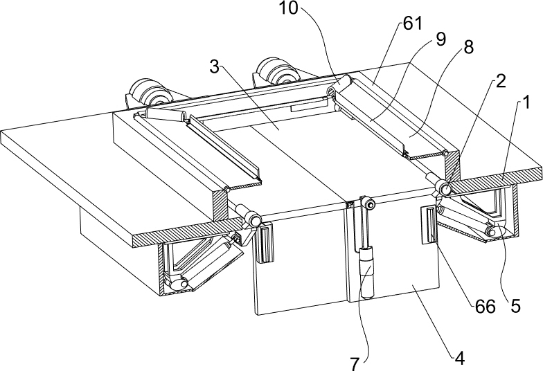
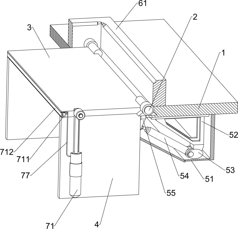
[0033] A hatch coaming structure of an ultra-large container ship, refer to Figure 1-Figure 7 , including a rotating shaft 2, a cover plate 3, a side plate 4, a driving assembly 5, a locking assembly 6 and a sealing assembly 7, the left and right sides of the upper part of the hatch plate 1 are rotatably provided with a rotating shaft 2, and the left and right two rotating shafts 2 are There is a cover plate 3. After the cover plate 3 is turned downward and closed, it can play the role of dustproof and waterproof, and prevent water from infiltrating into the cabin. Side plates 4 are welded on the front and rear sides of the bottom of the cover plate 3. The side panels 4 are arranged in a staggered manner, so that the side panels 4 will not collide when they are rotated upward. The bottom of the hatch panel 1 is provided with a drive assembly 5, the outer side of the side panel 4 is provided with a locking assembly 6, and the outer side of the side panel 4 is provided with a se...

Embodiment 2

[0039] On the basis of Example 1, refer to figure 1 , figure 2 , Figure 8 and Figure 9 , also includes a closing assembly 8, the closing assembly 8 includes a hinge plate 81, a rotating rod 82, a roller 83, a limit block 84 and a second spring 85, and the upper, front, rear, left, and right sides of the upper part of the fixed frame 61 are rotatable. 81. The hinge plate 81 can block the gap between the cover plate 3 and the hatch plate 1. The inside of the hinge plate 81 is rotatably provided with a rotating rod 82, and the rotating rod 82 is equipped with a rotating roller 83, and the cover plate 3 is upward. The rotation will come into contact with the roller 83 , the limit blocks 84 are welded on the front, rear, left and right sides of the upper inner side of the fixed frame 61 , the top of the limit blocks 84 are all in contact with the adjacent hinge plates 81 , and the bottom of the hinge plates 81 is between the inner wall of the fixed frame 61 . Both are provide...


PUM


Abstract

The invention relates to a hatch coaming structure, in particular to a hatch coaming structure of an ultra-large container ship. The invention aims to provide the hatch coaming structure of the ultra-large container ship, which can prevent water from seeping into a cabin. The ultra-large container ship hatch coaming structure comprises rotating shafts, cover plates, side plates, a driving assembly and the like, the rotating shafts are rotationally arranged on the left side and the right side of the upper portion of a hatch plate, the waterproof cover plates are arranged on the left rotating shaft and the right rotating shaft, and the side plates are arranged on the front sides and the rear sides of the bottoms of the cover plates. A driving assembly used for driving the cover plate to rotate upwards to be opened is arranged at the bottom of the hatch board. The first hydraulic cylinder serves as driving force to drive the cover plate to rotate upwards to be opened, and then the second hydraulic cylinder serves as driving force to drive the clamping plate to move inwards to clamp the clamping strip, so that the position of the cover plate is fixed, the cover plate is prevented from moving, and people can conveniently load goods into a cabin.

Description

technical field [0001] The invention relates to a hatch coaming structure of a ship, in particular to a hatch coaming structure of an ultra-large container ship. Background technique [0002] At present, when a fishing vessel is sailing, waves often turn over the deck, resulting in the displacement or loss of the hatch coaming. The waves are easily involved in the cabin and hurt the people in the cabin. [0003] Patent application CN203889003U, published on 20141022, discloses a glass fiber reinforced plastic fishing boat hatch enclosure structure, including the main deck of the glass fiber reinforced plastic fishing boat, the main deck is provided with a ship hatch that is convenient for personnel to enter and exit, and the outer frame of the cover plate and the hollow inner frame are connected. Filled with foam insulation material, the hatch coaming structure of the FRP fishing boat adopts the form of a concave groove structure to meet the self-locking effect of the hatch...

Claims


Application Information

Patent Timeline
Patent Type & Authority Applications(China)
IPC IPC(8): B63B19/14B63B3/54
CPCB63B19/14B63B3/54Y02A30/30
Inventor 刘银君张鹏陈金炉徐智沈强昇
Owner JIANGSU YANGZI XINFU SHIPBUILDING CO LTD
Why Eureka
Try Eureka