Method for deformation forming of metal composite foil and forming equipment

A metal composite and forming equipment technology, applied in metal processing equipment, forming tools, structural parts, etc., can solve the problems of increasing material cost, volume and weight of metal composite foil, large metal composite foil, prolonging manufacturing time, etc., and achieve high energy Effect of density, avoidance of wrinkles, good cooling properties

Pending Publication Date: 2022-08-05
VOLKSWAGEN AG
View PDF0 Cites 0 Cited by
  • Summary
  • Abstract
  • Description
  • Claims
  • Application Information

AI Technical Summary

Problems solved by technology

However this requires the use of larger quantities of relatively expensive aluminum, thereby increasing material cost, volume and weight of the metal composite foil
[0007] The hitherto known solutions have different disadvantages since they increase the manufacturing costs, lengthen the manufacturing time or make the metal composite foil unnecessarily larger or heavier

Method used


Image

  • Method for deformation forming of metal composite foil and forming equipment
  • Method for deformation forming of metal composite foil and forming equipment
  • Method for deformation forming of metal composite foil and forming equipment

Examples


Embodiment Construction

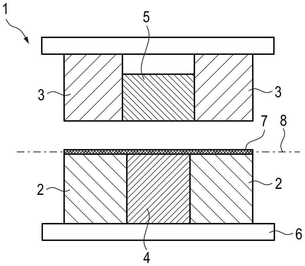
[0066] figure 1 A shaping device 1 according to the prior art is shown in a side sectional view. The forming apparatus 1 is constituted by a first sheet holder 2 , a first die 3 , a first punch 4 and a counter punch 5 . Furthermore, the forming apparatus 1 has a first drive 6 which is suitable for bringing the first sheet metal holder 2 and the first mould 3 towards each other and for fixing the metal composite foil 7 arranged in the pressing plane 8 there.

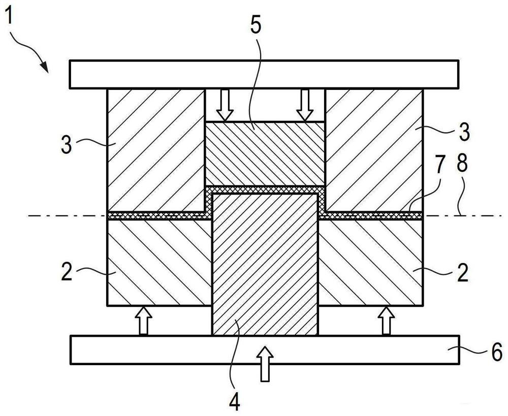
[0067] figure 2 shows according to figure 1 The forming apparatus 1 is in a state in which the metal composite foil 7 is deformed and formed in such a way that the punches 4 together with the counter punches 5 move upwards into the first die 3 in the drawing plane.

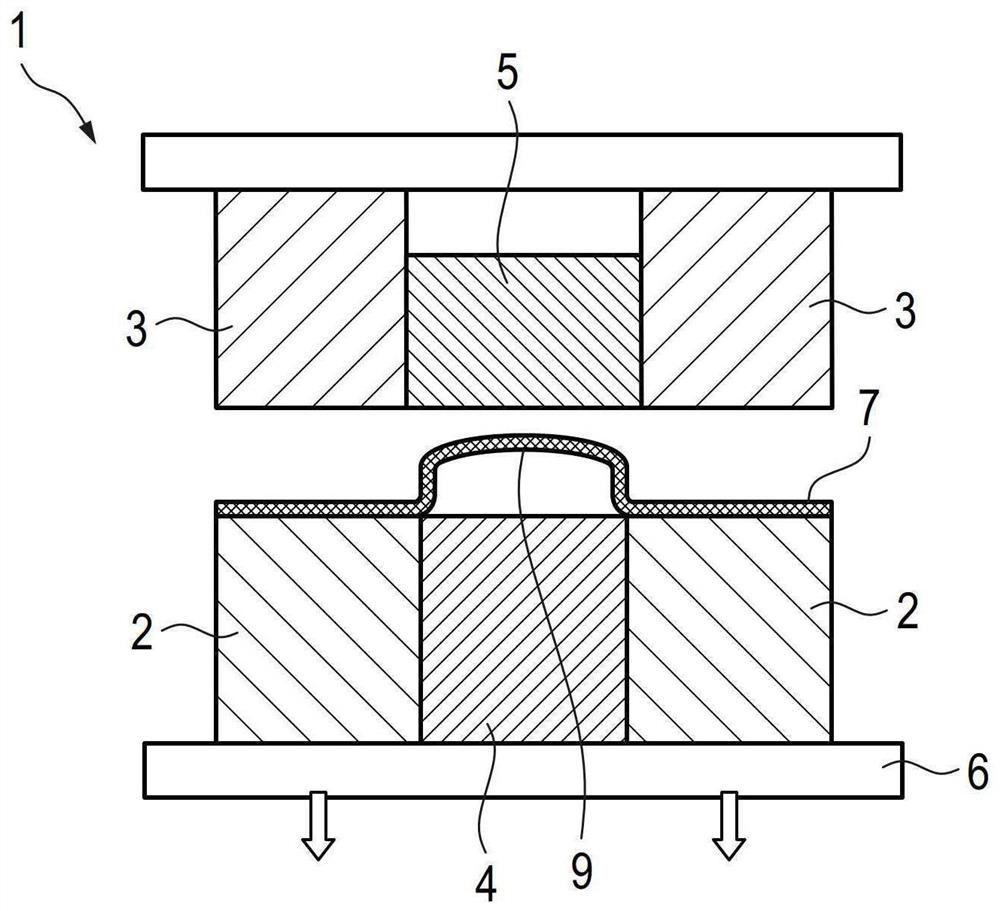
[0068] image 3 The situation is shown when the forming device 1 is opened after the deformation forming process, which means that all segments, namely the sheet holder 2, the die 3, the punch 4 and the counter punch 5, are moved back into their original...


PUM

PropertyMeasurementUnit
thicknessaaaaaaaaaa

Abstract

The invention relates to a method for shaping a metal composite foil (7) for battery cells (33), comprising at least the following steps: a) placing the metal composite foil (7) in a shaping device (1) having a plurality of sheet metal holders (2, 11), a plurality of forms (3, 10) and a first punch (4); b) fixing a first fixing region (13) of the metal composite foil (7) by closing the first sheet holder (3) and the first pattern (3); c) fixing a second fixing region (14) of the metal composite foil (7) by closing a second sheet holder (11) and a second pattern (10); d) deforming the second fastening region (14) at least partially in the first direction (16) by moving the second sheet holder (11) and the second pattern (10); e) deforming the deformation region (15) at least partially in the second direction (19) by moving the punch (4). The invention further relates to a shaping device (1) for shaping a metal composite foil (7) for a battery cell.

Description

technical field [0001] The present invention relates to a method for deforming a metal composite foil for a battery cell and a battery cell produced according to the method. Furthermore, the present invention also relates to a forming apparatus for deforming a metal composite foil for a battery cell. Background technique [0002] All that is required for the production of battery cells is that the metal composite foil is shaped so that it can form a receiving space for a cell stack with a high electrical storage density. In the prior art, for example, so-called pouch foils are known for this purpose, which are produced by deforming a composite of aluminum and plastic. In this case, at least one aluminum layer is connected to other flexible plastic layers to form a bag-like foil. Such aluminum laminate foils, however, sometimes have poor deep-drawing properties, so that cracks and wrinkles are always generated when the metal composite foil is deformed. Especially after the...

Claims


Application Information

Patent Timeline
Patent Type & Authority Applications(China)
IPC IPC(8): B21D33/00B21D24/00B21D24/04B21D24/10B21D37/10B21D37/16H01M50/119H01M50/122
CPCB21D33/00B21D24/005B21D24/04B21D24/10B21D37/10B21D37/16H01M50/119H01M50/122B21D22/24B21D22/22H01M50/105H01M50/129H01M50/121Y02E60/10
Inventor K.贾马达C.泰厄尔考夫C.施罗德
Owner VOLKSWAGEN AG
Why Eureka
Try Eureka